


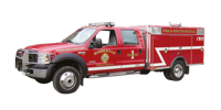
Brush Truck


Ford Cab & Chassis
Unit is to be installed on a Ford F550, Crew Cab, 4 x 4.
- GVWR : 17,950 lb
- Front Axle : 7,000 lbs
- Rear Axle : 13,500 lbs
- Maximum Payload : 10,100 lbs
- Rear limited slip axle
- Scuff plates
- Rear and Front Stabilizer suspension bar
- Extra Heavy Service Suspension Package
- Heavy duty towing package with 7 pin trailer wiring connector
The power train should consist of the following :
- Ford Power stroke V8, 6.4 L Turbo Diesel Motor
- 5 Speed TorqShift Automatic transmission
- Part-time four wheel drive
- Dual 130 Amp alternators
Interior requirements are as follows (XL package) :
- Black floor mats in place of carpeting
- Upfitter switches (4)
- 2-Heavy duty vinyl bucket seats instead of bench seats
- Air conditioning with high output fresh air heater
- Am/Fm Stereo with digital clock
- Tilt steering wheel.
Exterior requirements are as follows (XL Décor package):
- The chassis shall be painted by the chassis manufacturer according to the chassis manufacturer’s factory standards. The body builder shall not repaint the chassis. Cab to be Ford Fire Red (F1)
- Chromed front bumper
- New design front lights
- Argent grill
- Dual front tow hooks
- Driver and passenger manually telescoping trailer tow mirrors with power glass.
- The chassis exhaust system shall be extended to the rear of the right rear wheel.
- The tires should be a maximum traction mud / snow tire
- The wheel base should be 200” wheelbase
- Wheels to be primed grey
Major Standard Features :
- Two (2) front tow hooks
- Axle – Front Monobeam with coil spring suspension
- Battery – 750 CCA 78-AH
- Brakes – Anti-lock System (ABS)
- Dual instruments panel mounted cupholders
- Engine hour meter
- Exterior cargo light – Back of cab
- Front and rear stabilizer bars
- Fuel tank – 40 gallon capacity
- Grab handles – Driver and front passenger
- Manual transfer case and hubs (4 x 4)
- Power steering
- Roof clearance lights
- Solar tinted glass
- Steering damper
- Windshield wipers – interval
Safety & Security :
- Airbag – Driver and front passenger
- Belt-Minder safety belt reminder
- BlockerBeam – includes valance air dam
- Passenger airbag deactivation switch
The Fire Apparatus shall meet all the requirements of the NFPA 1906 standard while stationary on a grade of 20 percent in any direction.
Cab & Chassis Modification
Wheels to be polished forged aluminum such as Alcoa Classic 8 or equivalent.
Front bumper extension made with 1/8” bright polished diamond tread plate aluminum for the front mounted monitor.
Inside Doors Reflective
All driving and crew compartment doors shall have at least 96 in2 of reflective material affixed to the inside of each door.
Engine Speed Control Device
An automatic engine speed control device shall be installed to allow an increase in the engine speed when the apparatus is parked. (NFPA 1906, 5.2.1.4 requirement)
Stainless Steel Side Step Bars
One (1) set of 3" diameter stainless steel side step bars. Steps to be marine grade 304 prime stainless steel polished to a mirror finish with molded non-slip step pad.
Step area is compressed, rather than a cut out hole, to enhance strength and prevents interior corrosion.
Lifetime Limited Warranty
Lettering & Stripping
The finished apparatus shall be lettered to match the existing apparatus, the door logo shall be provided by the Fire Department. The Apparatus number shall be applied to the transverse compartment doors on each side in 8” numerals. The apparatus number shall be applied on the roof of the cab in large reflective numerals. 4” Reflective 3M stripping shall be applied on the Cab & Truck Bed as per NFPA.
Winch (9,500#) & Brush Guard
There shall be a 9500 lbs. WARN 9.5ti Thermometric removable electric winch. As per NFPA 1906 (13.2.2), the winch shall have a minimum wire rope length of 125 ft (38m) with a large latched hook. The wire rope will be 5/16’’ in diameter and shall be constructed of aircraft wire rope and galvanized to help resist corrosion.
Feature of the winch will include a 3 stage planetary gear system for fast line speed, cam action clutch disengages planetary gear system for free spooling and automatic load holding brake for strength and reliability.
There shall be a winch carrier to mount the winch with a Warn 2” front receiver mounted directly on cab & chassis frame without drilling. A rear mounted Class IV trailer hitch shall be securely attached to the chassis frame and shall include the 7-pin wiring trailer harness. Front and Rear Warn Quick Connectors and battery power leads to connect the winch shall be run to each of these locations for mounting of the winch. Dust Cover to be installed front and rear.
A remote with 25’ (7.6m) of cable shall be supplied (NFPA 1906, 13.3.1.1 requirement).
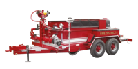
CET Flat Bed Body
One (1) custom Fire Application aluminum flat bed body, 132” (11’) long x 94’’ wide. The aluminum plate used in construction is 1/8” 3003-H22 polished aluminum alloy treadplate.
Body sub-frame is made from 6061-T6 aluminum tubes and channels. Sub-frame crossmembers are installed every 16”. The channel is 1-1/2” wide x 3” high x 3/16” thick. The body crossmembers shall be welded to the sub-frame main members.
The Body sub-frame main members consist of 6061-T6 Aluminum square tubing of 4” wide x 6” high x ¼” thick.
Aluminum Side designed to embed emergency lighting.
The body shall be attached to the chassis rails with a minimum of four (4) heavy duty “U” bolts. The body shall be separated from the chassis by 3/8” Teflon. Attachment of the body and sub-frame will allow the body to resist from all distortion and off road operational condition.
The body is a modular design to allow removal from the chassis for major repair or mounting on a new chassis.
All welding shall be done electrically using 5356 aluminum welding wire.
Rear vertical skirt will be made from 1/8” 3003-H22 polished aluminum alloy treadplate.
Rear skirt to include Signal, brake, reverse lights, D.O.T., license plate & NFPA steps.
Rear mudflaps are provided. Rear rubber mud flaps are provided. A bracket attached to the side of the muffler pipe end is installed to prevent any damaged that can occur to the mud flap.
Two (2) heavy duty tow eyes shall be installed at the rear of the body (NFPA 1906 requirement). The tow eyes will be fastened directly to each rear chassis frame rail. Hardware shall have a clear and unobstructed access.
The rear of the flat bed shall have two (2) non-skid rear steps for access to pump and controls. The rear steps shall be made so it can be folded up for use in rough terrain. All steps shall sustain a minimum static load of 500 lb (227 kg) without deformation (NFPA 1906 & 1901 compliant). Stepping height from the ground to the first step shall not exceed 24”.
Access handrails shall be provided where steps for climbing are located.
An angle of approach and an angle of departure of at least 20 degrees shall be maintained at the front and the rear of the vehicle when it is loaded.
This will be no exception to the body specifications. Pre-built commercial flat bed bodies are not acceptable.
Compartments
All compartments will be made with .125 mil bright polished diamond tread aluminum. Compartment doors to be made with smooth surface aluminum and painted red to match the Cab & Chassis colour.
All compartments seams is sealed with a pliable automotive body caulking.
All compartments shall have a minimum of one (1) louvered panel bolted into a wall to provide the proper airflow inside the compartment.
The overlap aluminum compartment doors shall be securely attached to the body with a full stainless steel hinge. Door openings shall be fitted with solid neoprene weather strip completely sealing the perimeter of the compartment door opening. Lift up door shall be installed with gas hold open struts.
Each compartments will have at least one (1) 12” long clear light tube. Each light tube to have a minimum brightness of 28,000 – 30,000 cd/m2 with an expected lifetime of 30,000 hrs.
There shall be a set of tracks for future installation of adjustable shelf(s) in each compartment. These tracks shall be installed vertically on the walls of the compartment(s) with holes every 1-1/4” for a multitude of height adjustment possibilities.
All door lock mechanisms shall be fully enclosed within the door panels to prevent fouling of the lock in the event equipment inside into the lock area.
The compartment doors shall have slam type latches with recessed stainless steel “D” ring handles.
The interior of compartments shall be finish painted in a light color splatter type scuff-resistant paint for durability and to help illuminate the contents.
Compartments shall have modular tile type flooring in the bottom and on all shelves.
R1 – L1 One (1) 32” long x 60” high x 20” deep on each side, with a 16” step-up to clear the chassis frame, and 44” wide across the frame. The compartment has a total side to side width of approximately 94” long an will be suitable for rescue tools storage. Door to open to a 90 deg. Angle from the closed position and will have a gas shock operators. Two (2) 12” tube lights are included in this transverse compartment.
R1 – L1 Compartments shall have four adjustable shelves, two on each side to the middle of the compartment and two roll out shelves, one on each side to the middle of the compartment.
L2 One (1) 66’’ long x 30’’ high x 14’’ deep compartment behind the chassis, located at the left side of the water tank. The compartment shall have a lift up door with gas hold open struts. One (1) 12” tube light is included in this compartment.
L2 Two SCBA brackets shall be provided and installed in the left side compartment. The compartment shall have space suitable for a 20lb ABC fire extinguisher.
R2. One (1) 66’’ long x 30’’ high x 14’’ deep compartments behind the chassis, located at the right side of the water tank. Lift up door with gas hold open struts One (1) 12” tube light is included in this compartment.
R2 One (1) Adjustable shelf to be installed in the driver side compartment. One (1) 12” tube light is installed under this shelf.
Rear Suction Hose Compartment
One (1) integrated to the platform compartment approximately 5’’ high x 24’’ wide x 124’’ long for suction hose storage. A flip down horizontally hinges door is furnished at the rear. The interior compartments is made from polished 3003-H14 alloy smooth plate. The compartment will be sufficient size for four 10’ lengths of 2-1/2” hard suction hose and pike pole storage.
Floating Strainer Compartment
One (1) compartment shall be supplied and installed at the left rear side of the truck bed with proper dimension to fit one (1) 2-1/2” Kochek floating strainer.
Left Storage Tray
A Storage Tray made from 1/8” aluminum diamond plate shall be supplied and installed on top of the left side bed compartments.
Dimension of the Storage Tray to be full length of the top compartment, 12” wide and the height to be level with the top of the transverse compartment.
The area shall be designed to prevent the accumulation of water and allow for ventilation to aid in drying hose in the storage area. Black Turtle Tiles to be installed and bolted on the floor.
Red canvas with snaps shall be installed on top of the Storage Tray along with rear protective net.
Right Storage Tray
A Storage Tray made from 1/8” aluminum diamond plate shall be supplied and installed on top of the right side bed compartments.
Dimension of the Storage Tray to be full length of the top compartment, 12” wide and the height to be level with the top of the transverse compartment.
The area shall be designed to prevent the accumulation of water and allow for ventilation to aid in drying hose in the storage area. Black Turtle Tiles to be installed and bolted on the floor.
Red canvas with snaps shall be installed on top of the Storage Tray along with rear protective net.
The right side hose tray shall have a 1-1/2” pre-connect elbow. There shall be a 1-1/2” valve piped from the discharge manifold to the hose tray pre-connect elbow using high pressure flexible hose. The valve shall be a fire type quarter turn self locking swing out valve with a handle.
Electrical components
A 12 volt electrical system is supply. The built in emergency light switch panel have a master switch plus individual switches for selective control. The switch panel is located in the cab on the driver’s side to allow for easy access. The switches on the dashboard is lighted rocker type.
The wiring is secured in place, readily accessible and protected against heat, water and physical damage.
All wiring will be run in heat and moisture resistant plastic convoluted split loom.
Grommets will be used where conductors or loom pass through metal.
Power control relays and solenoids shall have a direct current rating of 125 percent of the maximum current for which the circuit is protected.
Conductor insulation will conform to S.A.E. requirements. All circuit are protected by automatic reset circuit breakers.
All wiring furnished will conform to the national Electric Code.
All circuits will be wired in conformance with S.A.E. J1292, Automobile wiring standard.
All wiring will be function worded schematically.
A set (2) of electric diagram will be remit upon delivery.
Clearance, marker, license plate lights and reflectors will be furnished per D.O.T.
Signal, brake and reverse lights will be High Quality Grote Automotive lights recessed mount into rear aluminum skirt area of body per FMVSS 108 and CMVSS 108 requirements. Light to be Oval LED with chromed housing.
One (1) back-up alarm with a minimum rating of 97 decibels shall be provided at the rear of the apparatus. It will activate when the transmission is placed in reverse.
Door Ajar
One (1) door ajar warning light shall be provided and installed in the consol to indicate an open body compartment door. The light shall be properly marked with a sign “Warning Door Ajar”.
Compartment Lights switches
One (1) switch per compartment shall be installed so the compartment light(s) shall come on only when compartment door is open.
Battery charger
One (1) Auto Charger Kit. Location of the charger to be under front passenger seat. The Auto Charge kits include the Indicator, Automatic battery charger and Auto Eject with water proof cover. Model to be 091-39-12-S-Kit
In addition of this system, installation of one (1) duplex 110v straight three prong electric outlets wired to a Kussmaul 15 amp. Location to be on the rear of the center console.
Scene Lights
Two (2) 300W telescoping 12v scene lights mounted at the front of the Truck Bed. The light shall be single head design. One light mounted on each side will increase visibility around the apparatus during night or light operations. Model is to be Fire Research FCA512-D30. On/Off lamphead switch FCAoption-ON to be installed on each light head. The lights shall also be wired to separate switches on the center console.
One (1) Rear Unity scene light provided and mounted on the top of the rear water tank. Light to be Floodlight with a switch to be located on the light and at pump panel.
Reverse lights will be wired for use as rear scene lights with a switch located on the center console and a switch located near the pump panel.
Emergency lighting
One (1) NFPA Whelen Lightbar, Delta model, 56” long with red/clear/red lens. Lightbar to be mounted on the front top Cab & Chassis.
- 3 x Rotator with 2 Diamond Mirrors
- 2 x Alley Lights
- 2 x Front Take Down
The light bar is to include optional 6 lamps amber halogen arrow stick.
Mounted on front Ford grill, Two (2) Whelen 400 series Super Led, red, each with a chrome flange.
Mounted each side of the chassis, Two (2) Whelen 400 series Super Led, one (1) each side, red, each with a chrome flange.
Mounted each side of the body, Two (2) Whelen 400 series Super Led, one (1) each side, red, each with a chrome flange.
Mounted in the rear lower section of the body Two (2) Whelen 400 series Super Led, red, each with a chrome flange.
Siren & Speaker
One (1) Whelen, model # 295HFSA1, 100 watts electronic siren amplifier with PA and switch control center to be provided and installed.
One (1) Whelen, model # SA314P, 100 watt speaker, to be provided and mounted behind the Cab & Chassis front grill with proper mounting bracket.
Console
One CET aluminum fire application custom consol installed between seats with rocker switch. To be quickly identified and visible to the driver and passenger while seated, the rocker switches shall be installed on the top face of the console designed with a 40 deg. angle. This area shall be able to hold at least two rows of rocker switch. All switches shall be rocker style internally lighted and appropriately identified by panel mounted legends.
The first lighted rocker switch to be a red Master Optical Warning switch. A master body disconnect automatic switch, normally open contacts, shall be provided to disconnect all electrical loads not provided by the chassis manufacturer. The starter solenoids shall be connected directly to the batteries.
All rocker switch to have a green “On” indicator that is visible from the driver’s position shall be provided.
The consol will have an area to accommodate department map books, clipboards etc.. Area to be at least 13” long x 12” wide x 9” high.
The console also have an area for radio head & Siren installation.
One (1) 12 volt power outlet shall be mounted on the console.
A Hand-Held / Tripod Spot Lamp installed on the console. Features, 1,500,000 C.P. for high intensity output ; Hand held base opens to become tripod base for a work light ; H3, 100 watt halogen bulb ; 20 ft. Power cord.
All electrical components like breaker, relays, wiring etc. will be installed inside this customized consol and protected with an aluminium box. This consol will be design to easily gain access to those breaker, relays, wiring, etc.
Controls and switches that are expected to be operated by the driver while the apparatus is in motion shall be within convenient reach for the driver.
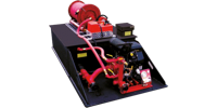
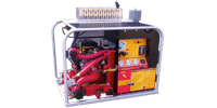
CET Fire Pumps Mfg Drop-In-Unit
Tank
The Water Tank shall be constructed of 1/2" thick polypropylene sheet stock with AccTuf™ resin. The material shall be of a certified, high quality, non-corrosive, stress relieved thermo plastic, black in colour with a textured finish, and UV stabilized for maximum protection. The skid type booster tank shall be of a standard configuration and shall be so designed to have complete modular slide in capability. All joints and seams are to be fully nitrogen welded and electronically tested for maximum strength. The unit shall incorporate transverse partitions manufactured for 3/8" PT2E polypropylene which shall interlock with a series of longitudinal partitions constructed of 1/2" PT2E polypropylene. All swash partitions shall be so designed to allow for maximum water and air flow between compartments and are fully welded to each other as well as to the inside of the tank.
The passenger side rear wall of the tank shall have a standard built in sight gauge 2" in width, and 70% transparent.
Fill tower and tank cover
The tank shall be equipped with a combination vent/overflow and manual fill tower. The fill tower shall be an 8" round by 6" high with a moulded drop-on type cover. The cover shall be fastened to the tower with a teather to prevent loss. The tower shall be located in the right rear corner of the tank. There shall be a vent / overflow installed inside and to the extreme rear of the tower approximately 2" down from the top. This vent / overflow shall be of a standard schedule 40 polypropylene pipe with minimum ID of 3". The vent / overflow shall be piped internally toward the front and exit out the front tank wall with a 1" extension past the front tank wall.
The tank cover shall be constructed of 1/2" thick PT2E polypropylene, black in color, UV stabilized, and incorporate an exclusive self locking design. The cover shall incorporate (4) 2" polypropylene for hold-down and lifting provisions. These dowels shall be tapered for ½" -13 threads to accommodate a lifting eye with a minimum security factor of 3 to 1. These dowel shall be welded into the transverse baffles, and will assist in minimizing cover flex during normal operation
Tank Capacity
The tank shall have a capacity of 400 U.S. gallons of water. The tank shall be covered by the ALL OUT No Fault Life Time Warranty.
Sump
The floor of the tank shall be manufactured from 3/4" PT2E polypropylene. There shall be one (1) sump as standard per tank. The sump shall be integral to the tank floor and be a minimum of 5/8" deep recessed into the floor. The sump shall not be visible from or protrude through the bottom of the tank.
Tank Outlets
There shall be two standard tank outlets located in the same vertical plane on the driver side rear wall of the tank. One (1) 3" female NPT tank to pump suction fitting and one (1) 1" female NPT tank fill fitting with flow deflector
Tank Mounting Blocks
The cover shall incorporate two (2) booster reel mounting blocks that shall be to accommodate two (2) each sliding nut fasteners. These mounting blocks shall be welded to the covers running from the rear edge of the tank forward.
Tank will be baffled in accordance with NFPA bulletin 1906 requirements.
Mounting
The Drop-In-Unit shall be mounted in a manner that allows access to the engine, pump, and auxiliary systems for routine maintenance. The Drop-In-Unit shall not be welded or otherwise permanently secured to other components.
Pump, PFP-24hpHND-MR
The pump shall be a CET PFP-24hpHND-MR single stage centrifugal pump, bolted directly to the engine, with a 2.5" NPT suction inlet, and a 1.5" NPT discharge outlet. The volute and pump head shall be a lightweight, high strength, seawater resistant, aluminum alloy. The impeller shall be a bronze enclosed type for maximum efficiency, fully machined and balanced. The engine crankshaft shall serve as the pump shaft, with the impeller mounted directly on the crankshaft. The shaft seal shall be self-adjusting, self lubricating, mechanical type. The pump shall be equipped with a brass drain cock.
The pump engine shall be equipped with an quieter exhaust venturi type primer capable of 15’ – 20’ lift for fast positive priming. The control for the primer shall be capable of being operated by a person operating controls at the primary pump operator’s position.
The pump shall be capable of a maximum discharge volume of 300 gpm @ 25 psi and 100 gpm @ 135 psi. At the center of the performance curve, the pump shall be capable of 160 gpm @ 100 psi.
Engine
The pump shall be driven by a 2 cylinder, gasoline engine powered, HONDA 24 horsepower V-twin overhead valve engine. The engine shall be air cooled, 12 volt electric start.
An external fuel tank shall be provided for the pump motor. It will be large enough to run the pump motor for one (1) hour at its rated capacity and pressure as per NFPA 1906, 8.10.1. Tank will be mounted with ease of filling in mind.
The engine shall be connected to the main battery of the truck.
Pump Controls
A control panel shall be supplied and installed on the pump. The controls shall consist of a start button, 2.5" diameter discharge pressure gauge and one work light. The Throttle lever, choke control and a low oil level shut down are part of the engine configuration.
The performances are base on a maximum altitude of 500ft and any higher elevation will lower the pump performance. The standard engine performance drop are 3% for every 1000 ft
Centerline of any control shall be no more than 72 in. vertically above the ground or platform that is designed to serve as the operator’s standing position.
The pump will be permanently mounted at the rear of the flat bed body.
Scotty Foam System
There shall be a Scotty model 4071 around the pump foam eductor / mixer installed integral to the pump. The eductor shall be plumbed from the foam cell with ½" flexible reinforced tubing to throughout the eductor to a suction fitting on the pump impeller housing. The eductor shall be calibrated to educt foam concentrate at variable percentage into a discharge manifold flowing 15, 30, 50 and 70 gal. per min. The eductor shall be capable of a discharge of a 1% foam solution at specified flows.
10 gallon Drop-in integrated foam cell will be included. A label that reads “Foam” shall be placed at any foam concentrate tank fill opening.
Booster Reel
One (1) 12v Electric Rewind Booster Reel
One (1) 12v electric rewind booster reel capable of handling 200' of 1" diameter booster hose. The reel shall have a push button rewind control and a backup geared crank rewind handle. The reel shall be equipped with a 1" NPT 90 degree swivel inlet, and a 1" NST outlet riser. The reel shall be manufactured of steel and shall be primed and painted red. Reel to be installed on the rear right side of the truck bed.
200 feet of 1” Neidner forestry booster hose and an Akron 1704 1” TurboJet Nozzle with pistol grip shall be provided and installed.
Booster Reel Rollers
One high mounted roller and spool assemblies shall be furnished and installed facing rear of the truck.
Front Mounted Monitor
A Elkhart Sidewinder or equivalent monitor shall be supplied and installed at the front of the truck.
An electronic controlled monitor shall be installed on the front of the vehicle. It shall be installed off center on the passenger side of vehicle. Plumbing shall be 1.0” high pressure hose.
The discharge shall be equipped with automatic drain valve to prevent freezing in cold climate, and shall open whenever the pressure in the discharge line drops below 5 Psi.
The drain shall be located in areas that will allow the entire line to drain effectively. More than one drain shall be used in line that are uneven along their length.
The outlets of the drain valve shall be extended with hoses to below the chassis frame rails.
Included in the monitor package shall be :
Ability to charge monitor from cab location with an electric valve. Joystick mounted on center console accessible by both driver and passenger side. Joystick shall control up/down, left/right and fog/straight stream operation.
Water level, MC Product mini display, shall be installed at the Cab & Chassis console.
The monitor shall include a 15 gpm constant flow nozzle with electronic straight stream to wide fog pattern control.
Plumbing and Valves
Intake and discharge piping shall not interfere with the routine maintenance of the pump, engine, or auxiliary systems and shall not unduly restrict the servicing of these components.
Suction Piping
All piping shall be schedule 40 steel piping, painted red. The suction piping shall consist of a 2.5" tank to pump line with a 2.5" flexible rubber hump hose to minimize flex and vibration between the pump and the tank. RIGID PIPING SHALL NOT BE ACCEPTABLE. Between the tank and the pump there shall be a 2.0" Fire Type, quarter turn self-locking swing out valve with handle. This valve shall remain open to pump from the tank. This pipe shall have a tee into the suction side of the pump, and shall continue to the rear of the truck for overboard suction.
For ease of operation, a push/pull control rod shall be installed with a cast brass “Tee” handle for the inlet located between the tank and the pump.
The overboard suction connection shall have a 2.5" NST male adapter w/cap with retaining cable. To draft, the tank to pump valve shall be closed, a suction hose connected to the overboard suction connection and placed in a static water supply, and the primer activated.
Discharge Piping
All piping shall be schedule 40 steel piping or high pressure flexible hose. A 2.5" X 2.5" square steel manifold shall be piped directly to the discharge outlet of the pump. Attached to this discharge manifold, by means of welded steel pipe nipples, shall be all the discharge valves. All piping shall be painted red to match the pump.
For ease of operation and maintenance All valves larger than 1" shall be Fire Type, quarter turn self-locking swing out valve with handle. Any valve 1" or smaller shall be standard plumbing style valves.
Tank Fill
There shall be a 1" valve piped from the discharge manifold as a means for refilling the tank. The valve shall be an industrial, quarter turn valve handle and 1" NPT threads, and shall be connected to the tank fill port by 1" high pressure flexible hose.
Discharge to Booster Reel
There shall be a 1" valve piped from the discharge manifold to the booster reel. The valve shall be an industrial, quarter turn valve handle and 1" NPT threads, and shall be connected to the reel by 1" high pressure flexible hose.
2.5" Discharge to Rear
There shall be one (1) 2.0" valve piped from the discharge manifold to the rear of the truck bed. The valve shall be an Fire Type, quarter turn self-locking swing out valve with a handle and 2.5" NST threads. The valve shall be furnished with a 2.5" cap and chain.
Garden Hose Discharge
There shall be a standard garden hose valve piped from the manifold of the pump.
1" Tank Drain
There shall be a 1" valve piped from the tank drain fitting to the rear of the truck bed. The valve shall be an industrial, quarter turn valve with a handle and 1" NPT female threads.
The Drop-In-Unit electricity will be connected directly to the main battery of the chassis.
Approximate weight of the Drop-In-Unit including hose reel(s) and full of water and other liquids shall be given before production.
Testing
The pump shall be tested after the pump and all its associated piping and equipment have been installed on the fire apparatus. The tests shall be conducted at the manufacturer’s approved facility.
The testing shall include at least the pumping tests, the priming device test, the vacuum test. The water tank-to-pump flow teat, and the piping integrity test.
Manufacturer’s discretion
Materials, parts, or procedures used are subject to change at manufacturer's discretion at any time to provide equal or better products.
Complete apparatus built accordingly to NFPA 1906 & DOT Compliant.
