


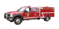
Brush Truck


Ford Cab & Chassis
Unit is to be installed on a Ford F550, Crew Cab, 4 x 4.
- GVWR : 17,950 lb
- Front Axle : 7,000 lbs
- Rear Axle : 13,500 lbs
- Maximum Payload : 10,100 lbs
- Ambulance Package
- Rear limited slip axle
- Scuff plates
- Rear and Front Stabilizer suspension bar
- Extra Heavy Service Suspension Package
- The power train should consist of the following:
- Ford Power stroke V8, 6.4 L Turbo Diesel Motor
- 5 Speed TorqShift Automatic transmission
- Part-time four wheel drive
- Dual 130 Amp alternators
- Interior requirements are as follows (XL package):
- Black floor mats in place of carpeting
- Upfitter switches (4)
- 2-Heavy duty vinyl bucket seats instead of bench seats
- Air conditioning with high output fresh air heater
- Am/Fm Stereo with digital clock
- Exterior requirements are as follows (XL Decor package):
- The chassis shall be order standard Ford White CET Fire Pumps, Mfg. will re-paint the lower of the apparatus including fenders and doors & excluding hood, to create a two (2) tone cab with a paint to match Borden Yellow #81639.
- Chromed front bumper
- New design front lights
- Argent grill
- Dual front tow hooks
- Mirrors, manually telescoping trailer tow with manual glass and two-way fold
- The chassis exhaust system shall be extended to the rear of the right rear wheel.
- The tires should be a maximum traction mud / snow tire
- The wheel base should be 176.2” wheelbase
- Wheels to be standard Ford Steel and Painted Job Color to match PPG Red #51121
- Major Standard Features:
- Two (2) front tow hooks
- Axle – Front Monobeam with coil spring suspension
- Battery – 750 CCA 78-AH
- Brakes – Anti-lock System (ABS)
- Dual instruments panel mounted cupholders
- Engine hour meter
- Exterior cargo light – Back of cab
- Front and rear stabilizer bars
- Fuel tank – 40 gallon capacity
- Grab handles – Driver and front passenger
- Manual transfer case and hubs (4 x 4)
- Power steering
- Roof clearance lights
- Solar tinted glass
- Steering damper
- Windshield wipers – interval
- Safety & Security:
- Airbag – Driver and front passenger
- Belt-Minder safety belt reminder
- BlockerBeam – includes valance air dam
- Passenger airbag deactivation switch
The Fire Apparatus shall meet all the requirements of the NFPA 1906 standard while stationary on a grade of 10 percent in any direction.
Stainless Steel Side Step Bars
One (1) set of 3" diameter stainless steel side step bars. Steps to be marine grade 304 prime stainless steel polished to a mirror finish with molded non-slip step pad.
Step area is compressed, rather than a cut out hole, to enhance strength and prevents interior corrosion.
Lifetime Limited Warranty
Plastic step pad shall be covered with a Stainless Steel non-slip texture cover. Brand to be RealWheels model #RW420-2.
Lettering & Stripping
The finished apparatus shall be lettered to match the existing apparatus, the door logo shall be provided by the Fire Department. The Apparatus number shall be applied to each side of the chassis hood. 4” Reflective 3M stripping shall be applied on the Cab & the truck bed as per NFPA.
At least 50 percent of the cab and body length on each side, at least 50 percent of the width of the rear, and at least 25 percent of the width of the front of the apparatus shall have the reflective material affixed to it.
Chevron Striping
Six (6) inch chevron stripping shall cover the entire rear of the apparatus
Inside Doors Reflective
All driving and crew compartment doors shall have at least 96 in2 of reflective material affixed to the inside of each door.
Engine Speed Control Device
An automatic engine speed control device shall be installed to allow an increase in the engine speed when the apparatus is parked. (NFPA 1906, 5.2.1.4 requirement)
An interlock shall prevent the operation of this engine speed control device unless the parking brake is fully engaged and the transmission is in neutral or park, or unless the engine speed control device is used with chassis engine driven components, in which case it shall be interlocked with the engagement of those components.
Polybody
The body shall consist of a left and right side module with doors. In addition, there shall be a formed metal header panel, threshold panel and floor panel. These components shall be assembled to form the modular body and shall be supported by a stainless steel subframe weldment. All components of the body shall be bolted together to allow for easy replacement. Threaded inserts shall be installed into all blind mounting holes. All other fasteners shall be stainless steel.
Material
The material used to construct the body side modules and doors shall be extruded copolymer polypropylene made from PolymarCo-PP™ resin.
Body & Compartments mounting
The compartment floors shall be of sweep out design for easy cleaning and have provision for drainage of moisture.
A utility style radiuses wheel opening shall be provided. An angle of departure of at least 20 degrees shall be maintained at the rear of the vehicle when it is loaded.
The rear wheel wells shall be radius cut with HARD FLEXIBLE RUBBER fenderettes installed at well opening.
A bright, anodized aluminum rub rail extrusion shall be bolted on both sides of the body below the compartment to protect the body from minor scrapes.
Two (2) pair of tow hooks to be installed, one (1) pair in the lower front of the chassis (Supplied by Ford), and one (1) pair in the rear of the body above the rear compartment.
Two (2) Anti-Slip grab rails, one (1) on each rear box type compartment. Grab rail shall be extruded polished aluminum (Bright Anodized) tube with rubber inserts providing maximum gripping ability.
Passenger side body module
There shall be a multi-compartment body module constructed from ½” PolymarCo-PP™ resin to form 3 compartments on the passenger side of the body. There shall be a single door compartment ahead of the rear wheels, a single door compartment over the rear wheels and a single door compartment behind the rear wheels. A utility style radiuses wheel opening shall be provided. Flush fuel filler doors shall be provided as required with removable inner pockets .Compartment dimensions shall be as follows
| Width | Depth | Height | |
|
Compartment ahead rear wheels |
35” |
21-1/2” |
52” |
|
Compartment behind rear wheels |
32” |
21-1/2” |
52” |
|
Compartment over rear wheel |
45” |
21-1/2” |
36” |
Driver side body module
There shall be a multi-compartment body module constructed from ½” PolymarCo-PP™ resin to form 3 compartments on the driver side of the body. There shall be a single door compartment ahead of the rear wheels, a single door compartment over the rear wheels and a single door compartment behind the rear wheels. A utility style radiuses wheel opening shall be to provided. Compartment dimensions shall be as follows
| Width | Depth | Height | |
|
Compartment ahead rear wheels |
35” |
21-1/2” |
52” |
|
Compartment behind rear wheels |
32” |
21-1/2” |
52” |
|
Compartment over rear wheel |
45” |
21-1/2” |
36”
|
Rear
One (1) integrated to the platform compartment approximately 5’’ high x 24’’ wide x 113’’ long for suction hose storage and folding ladders or pike poles. A flip down horizontally hinges door is furnished at the rear. The interior compartments is made from polished 3003-H14 alloy smooth plate. Steel frame underneath Drop-In-Unit shall not be acceptable
Upper section of the body
Passenger side shall have one storage hose tray made from aluminum diamond plate.
Top canvas w/rear protective net will be installed. One adjustable divider shall be installed in this compartment area.
Driver side shall have one (1) hose storage compartment to hold a minimum of 1-3/4” x 750’ of hose. Top canvas w/rear protective net will be installed.
All area shall be designed to prevent the accumulation of water and allow for ventilation to aid in drying hose in the storage area. Black Turtle Tiles to be installed and bolted on the floor.
Upper section will be made from .125” high bright aluminum diamond plate.
Roll-up Doors Compartment
All compartments shall be equipped with Amdor brand roll-up doors complete with the following features: door ajar switch, aluminum double wall slats with continuous ball & socket hinge joint and recessed slat seal, double wall reinforced bottom panel with stainless steel lift bar latching system, reusable slat shoes with positive snap-in securement, one-piece aluminum door track / side frame, top gutter with non-marring seal, non-marring side seals, bottom seal, with all wear component material to be Type 6 Nylon.
Roll-up doors to be anodized gray.
Upper roof area & extending down over side approx. 2” to the compartment doors and then forming a drip rail above doors.
Compartment ventilation
All compartments shall be ventilated through an integrated positive pressure vent system allowing for movement of air between compartments. Vent outlet at the front of the side compartment modules shall provide a water resistant entry and exit for air.
Subframe
A stainless steel subframe weldment shall be fabricated from tubing and formed sheet metal to provide a mounting platform for the body side modules and the floor. There shall be outriggers extending out and down from the sub frame to provide support to the side pack floors. There shall be four (4) outriggers supporting each side module. There shall be common attachment points along the length of the sub frame for mounting it to the truck chassis. The finish on the subframe shall be a semi-flat black urethane enamel.
Body header panel
A formed .125» high bright aluminum diamond plate panel shall be provided at the front of the body and shall extend the full width and height of the body to provide full frontal protection to the body side modules. The header panel shall be fastened to both body side modules. Louvers shall be installed in each side of this header panel to provide air to vent the compartments. A second inner reinforcement panel shall be formed behind the header panel at the front of the cargo area. It shall have three (3) integral reinforcing ribs to provide maximum strength.
Body threshold panel
A formed .125» high bright aluminum diamond plate panel shall be provided at the rear of the body and shall incorporate a formed backsplash lip under the cargo floor. It shall extend across the lower width of the body under the cargo floor area. This panel shall be fastened to both body side modules.
Cargo floor
The floor of the cargo area shall be formed from .125» high bright aluminium diamond plate and shall extend the full width between the body side modules. The floor shall incorporate formed vertical flanges on each side, which are fastened to the body side modules. All compartment floors will be covered with Plastic Tiles
Adjustable shelf tracking
Each compartment shall have four (4) aluminum tracks fastened to the interior sidewalls to provide an adjustable mounting surface for shelving.
Adjustable shelving
There shall be adjustable shelving formed from .125 thick smooth aluminum sheet. Each shelf shall be fastened to the tracking using four (4) adjustable shelf clips and stainless steel hardware.
Compartment Location
| Number of shelves | |
| Left Front Cmpt | 1 |
| Right Front Cmpt | 1 |
| Left Rear Cmpt | 1 |
| Right Rear Cmpt | 1 |
Bumper
A full width bumper shall be provided at the rear of the body formed from 12 gauges steel. Steel brackets shall be incorporated to attach the bumper to the vehicle chassis.
An aluminum grip strut with radius corners shall be fastened to the steel brackets. Protection between steel and aluminum will be added.
Electrical components
A 12 volt electrical system is supply. The built in emergency light switch panel have a master switch plus individual switches for selective control. The switch panel is located in the cab on the driver’s side to allow for easy access. The switches on the dashboard is lighted rocker type.
The wiring is secured in place, readily accessible and protected against heat, water and physical damage.
All wiring will be run in heat and moisture resistant plastic convoluted split loom.
Grommets will be used where conductors or loom pass through metal.
Power control relays and solenoids shall have a direct current rating of 125 percent of the maximum current for which the circuit is protected.
Conductor insulation will conform to S.A.E. requirements. All circuit are protected by automatic reset circuit breakers.
All wiring furnished will conform to the national Electric Code. All wiring will be function worded schematically.
All circuits will be wired in conformance with S.A.E. J1292, Automobile wiring standard.
A set (2) of electric diagram will be remit upon delivery.
Back Up Alarm
One (1) back-up alarm that meets the type D (87 dba) requirements of SAEJ994 shall be provided at the rear of the apparatus. It will activate when the transmission is placed in reverse.
DOT lighting:
Lighting and reflectors shall be provided to comply with federal motor vehicle safety standard FMVSS-108. This shall include Whelen #70J000CR LED Back-up lights, #70A00TAR LED Turn Arrow & #70R00BRR LED Brake on the rear of each body side module. These lights shall be mounted to the body with a chromed bezel and appropriate gasketing. The street side module shall have a license plate light and mounting provisions for license plate under it.
Note: on bodies over 80” wide, a red triple clearance light cluster shall be provided in the lower center of the rear panel. All wiring shall be in split convoluted loom to form a harness.
An aluminum protection cover shall be provided over the harnesses at the inside rear body panel to guard against damaging the harness due to shifting cargo in the compartments.
Compartment lighting
Each compartment shall have Amdor LED rope lighting mounted in the vertical position and installed on the side Amdor extrusion. All wiring shall be properly sized, GXL, copper stranded, function coded and concealed in a split convoluted loom harness and routed through the body. Automotive type snap in loom clips shall hold harnesses securely in place.
Drop-In Unit lighting
There shall be a Weldon Series 2000 flat backlight installed in the pump area to provide lighting for the pump operator.
There shall be a switch on the pump operator’s panel installed to enable the rear backup lights as well as a pump area light to turn on without the vehicle being in reverse gear.
Emergency Lightning
One (1) 55” Super LED Whelen Lightbar, Liberty model # SLN2VLED. Lightbar to be mounted on the cab roof.
- 4 x Red Super LED Corners
- 2 x Red Super LED Inner
- 2 x White Super LED Inner
- 2 x Front Facing Takedown lamps
- 2 x Side Alley lamps, one (1) each side
For Blocking Right-of-Way Mode of operation, white Super LED Inner lights (2) shall be turned off when parking brake is applied.
Mounted on front Cab & Chassis grill, Two (2) Whelen 700 series SUPER LED, red with clear lens, each with a chrome flange.
Mounted each side of the chassis, Two (2) Whelen 700 series SUPER LED, one (1) each side, red with clear lens, each with a CAST Product’s angled polished aluminum housing to give the affect of the light being vertically aligned.
Mounted each side of the body, Two (2) Whelen 700 series SUPER LED, one (1) each side, red with clear lens, each with a chrome flange.
Mounted in the rear upper section of the body Two (2) Whelen 700 series SUPER LED, red with clear lens, each with a chrome flange.
Mounted in the rear lower section of the body Two (2) Whelen 700 series SUPER LED, red with clear lens, each with a chrome flange.
Traffic Advisor
There shall be one (1) Whelen Model #TAM83 Eight lamps TIR3 Super LED traffic advisor mounted on the rear upper section of the apparatus body, the split design of the traffic advisor shall allow for one (1) piece to be mounted on the left side of the body and one (1) piece to be mounted on the right side of the body and be controlled in the cab center console.
Siren & Speaker
One (1) customer supplied Karson brand electronic siren amplifier installed into custom made console.
One (1) Whelen, model # SA315P, 100 watt speaker, to be provided and mounted on the front bumper with SAK1 universal mounting bracket.
Console
One aluminum fire application custom consol installed between seats with rocker switch. To be quickly identified and visible to the driver and passenger while seated, the rocker switches shall be installed on the top face of the console designed with a 40 deg. angle. This area shall be able to hold at least two rows of rocker switch. All switches shall be rocker style internally lighted and appropriately identified by panel mounted legends.
The first lighted rocker switch to be a red Master Optical Warning switch. A master body disconnect automatic switch, normally open contacts, shall be provided to disconnect all electrical loads not provided by the chassis manufacturer. The starter solenoids shall be connected directly to the batteries.
All rocker switch to have a green “On” indicator that is visible from the driver’s position shall be provided.
The console will have an area to accommodate department map books, clipboards etc..
The console shall also have an area for radio head & Siren installation.
Map Light, 12” gooseneck Halogen, Havis Shield, model C-MAP-S, side mounted on the cab console.
A Hand-Held / Tripod Spot Lamp installed on the console. Features, 1,500,000 C.P. for high intensity output ; Hand held base opens to become tripod base for a work light ; H3, 100 watt halogen bulb ; 20 ft. Power cord.
All electrical components like breaker, relays, wiring etc. will be installed inside this customized consol and protected with an aluminium box. This consol will be design to easily gain access to those breaker, relays, wiring, etc.
Controls and switches that are expected to be operated by the driver while the apparatus is in motion shall be within convenient reach for the driver.
A final layout shall be done at the pre-construction meeting.
Console to be painted black Herculiner style scratch free finish.
Paint
The paint or coating, including any primer, shall be applied in accordance with the paint or coating manufacturer’s recommendation.
Body Modules shall be thoroughly washed with grease cutting solvents prior to any sanding. After the body has been sanded and the minor imperfections corrected, the body shall be washed again with a solution to remove any contaminants on the surface. The first coating to be applied is a universal plastics adhesion promoter followed with three coats of primer. The primer coat is to be hand sanded with 320 grit sandpaper to insure maximum gloss of the paint. The last step is the application of at least three coats of PPG Concept Acrylic Urethane paint.
The body and lower chassis (Upper Chassis to be standard Ford Oxford White) paint shall match PPG Red #51121.
All exposed ferrous metal surfaces that are not plated or stainless steel shall be cleaned and prepared and shall be painted or coated.
The interior of the body compartments shall be left in their natural color of white.
Others
Manufacturer shall install customer supplied air pack mounting brackets (4) & customer supplied Vulcan light boxes (5)
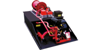
Drop In Unit
Water Tank
The water tank shall be constructed of 1/2" thick polypropylene sheet stock with PolymarCo-PP™ resin. Water tank shall be welded with Heavy Duty extruded joint. The material shall be of a certified, high quality, non-corrosive, stress relieved thermo plastic, black in colour with a textured finish, and UV stabilized for maximum protection. The skid type water tank shall be of a standard configuration and shall be so designed to have complete modular slide in capability. The unit shall incorporate transverse partitions manufactured for 3/8" PT2E polypropylene which shall interlock with a series of longitudinal partitions constructed of 3/8" PT2E polypropylene. All swash partitions shall be so designed to allow for maximum water and air flow between compartments and are fully welded to each other as well as to the inside of the tank. The passenger side rear wall of the tank shall have a standard built in sight gauge 3" in width, and 70% transparent.
Fill Tower & Tank Cover
The tank shall be equipped with a combination vent/overflow and manual fill tower. The fill tower shall have a 8" x 8" x 8" square hinged type cover. The tower shall be located in the right rear corner of the tank. There shall be a vent / overflow installed inside and to the extreme rear of the tower approximately 2" down from the top. This vent / overflow shall be of a standard schedule 40 polypropylene pipe with minimum ID of 3". The vent / overflow shall be piped internally toward the front and exit out the front tank wall with a 1/2" extension past the front tank wall. The tank cover shall be constructed of 1/2" thick PT2E polypropylene, black in color, UV stabilized.
Tank Capacity
The tank shall have a capacity of 300 U.S. gallons of water.
Sump
The floor of the tank shall be manufactured from 3/4" PT2E polypropylene. There shall be one (1) sump as standard per tank. The sump shall be integral to the tank floor and be a minimum of 3/8" deep recessed into the floor. The sump shall not be visible from or protrude through the bottom of the tank.
Tank Outlets
There shall be two standard tank outlets located in the same vertical plane on the driver side rear wall of the tank. One (1) 2-1/2" female NPT tank to pump suction fitting and one (1) 1-1/2" female NPT tank fill fitting with flow deflector
1" Tank Drain
There shall be a 1" tank drain to the rear side of the tank with a brass plug.
Tank Mounting Blocks
The cover shall incorporate two (2) booster reel mounting blocks that shall accommodate two (2) each sliding nut fasteners. These 4" large mounting blocks shall be welded to the covers running from the rear edge of the tank forward to the front edge.
Skid Base
There shall be a full width skid base manufactured of 3/4" PT2E polypropylene welded to the tank. This base shall be 48" wide by 96" long and shall extend 34" past the tank in the rear to allow for pump mounting. The pump mounting area shall be supported by ½" PT2E polypropylene gussets approximately 15" high by 32" long. The gussets shall be equipped with 2" holes to assist in lifting the unit. The mounts shall allow for the truck to be secured directly to a truck bed without the need for any skid frame work underneath.
Tank will be baffled in accordance with latest NFPA requirements.
Water Tank Indicator
Fire Research TankVision model WLA200-A00 tank indicator kit shall be installed. The kit shall include an electronic indicator module, a pressure sensor, and a 10' sensor cable. The indicator shall show the volume of water in the tank on nine (9) easy to see super bright LEDs. A wide view lens over the LEDs shall provide for a viewing angle of 180 degrees. The indicator case shall be waterproof, manufactured of aluminum, and have a distinctive blue label.
The program features shall be accessed from the front of the indicator module. The program shall support self-diagnostics capabilities, self-calibration, and a datalink to connect remote indicators. Low water warnings shall include flashing LEDs at 1/4 tank, down chasing LEDs when the tank is almost empty, and an output for an audio alarm.
The indicator shall receive an input signal from an electronic pressure sensor. The sensor shall be mounted from the outside of the water tank near the bottom. No probe shall place on the interior of the tank. Wiring shall be weather resistant and have automotive type plug-in connectors.
Location of water tank indicator shall be: Pump Panel Area
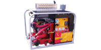
Pump
The pump shall be a CET DI-PFP-21hpDSL-MR single stage centrifugal pump, bolted directly to the engine, with a 2.5" NPT suction inlet, and a 1.5" NPT discharge outlet. The volute and pump head shall be a lightweight, high strength, seawater resistant, aluminum alloy. The impeller shall be a bronze enclosed type for maximum efficiency, fully machined and balanced. The engine crankshaft shall serve as the pump shaft, with the impeller mounted directly on the crankshaft. The shaft seal shall be self-adjusting, self lubricating, mechanical type. The pump shall be equipped with a brass drain cock.
The pump piping shall be flexible to prevent any breakage caused by vibration.
The pump shall be capable of a maximum discharge volume of 240 GPM @ 50 PSI, and a maximum discharge pressure of 175 PSI while pumping 60 GPM. In the center of the performance curve, the pump shall be capable of pumping 110 GPM at 150 PSI and 170 GPM at 100 PSI.
Engine
The pump shall be driven by a 3-Cylinder Kubota diesel powered, 21 horsepower engine. The engine shall be liquid cooled, 12 volt electric start. The engine shall be fueled from the chassis fuel source. The engine shall be connected with a quick disconnect weather proof style connection.
Pump Controls
A control panel shall be supplied and installed on the pump located at the rear of the skid unit. The control panel shall be manufactured from aluminum and completely covered with a black plastic plate. The Control Panel shall consist of a master switch, start button, engine stop, oil pressure, glow plug and engine temperature warning lights, 2.5" diameter pump discharge pressure and 2.5” dia. Pump intake liquid filled gauges, primer control, throttle lever and illumination for controls with the installation of one tube light.
All pump controls and gauges shall be properly marked with white letters engrave in the black plastic plate.
Exhaust priming system
The pump engine shall be equipped with an exhaust venturi type primer capable of 15' - 20' lift for fast positive priming.
Suction Piping
All piping on the suction side shall be made of steel (welded joints) schedule 40. The suction piping, the pump and the discharge shall be tested to 400 PSI.
The suction piping shall consist of a 2.5" tank to pump line with a 2.5" flexible rubber hump hose to minimize flex and vibration between the pump and the tank.
Between the tank and the pump there shall be a 2.5" industrial valve. This valve shall remain open to pump from the tank. This pipe shall have a tee into the suction side of the pump, and shall continue to the rear of the truck for overboard suction.
The overboard suction connection shall have a 2.5" NST male adapter and a 2.5" NSTF cap with retaining cable.
Overboard Suction Fire Grade Valve
The specified overboard suction will be equipped with a 2" fire grade drop out style valve. This valve will terminate with a 2 1/2" NST male connection and be protected with a cap and chain.
This valve will be equipped with an handle for ease of use.
Tank to Pump Fire Grade Valve
The specified industrial valve for the tank to pump will be deleted and a 2" fire grade drop out style valve shall be utilized.
This valve shall be equipped with an handle and have a "T" handle extension to the rear of the platform for ease of use.
Work Line Side of Manifold
On the drivers side of the manifold there will be as standard two (2) 1" NPT and two (2) 1 1/2" NPT discharge outlets.
Other Valves
Other openings will be utilized accordingly when pre-connects, booster reels and other accessories that require pressurized water are specified.
Discharge Valves
All valves larger than 1" shall be a fire service type drop out style ball valve which shall have a hard-coated anodized, high-strength, light-weight aluminum alloy body with rugged stainless steel ball and two PTFE seats.
The valves shall be capable of bi-directional flow with a minimum working pressure rating of 250 psig.
All stainless steel parts shall be made from 300 series material. The valves shall NOT require lubrication of the seats or any other internal waterway component and shall be capable of swinging out of the attached waterway plumbing for easy maintenance, with the removal of six (6) to eight (8) bolts.
Any required valve 1" or smaller, unless other wise specified, shall be a standard plumbing style industrial ball valve.
TSC Control Handle for all discharge & suction valves
Discharge Manifold
There shall be a discharge manifold plumbed directly to the discharge side of the pump to incorporate discharges at the rear of the unit.
This discharge manifold shall be 2" x 2" square minimum and be welded on all sides to prevent leakage.
The manifold will be made from industrial galvanized steel and painted red in color.
Discharges to Rear of Unit
A 1 1/2" fire grade valve drop out style with handle and 1 1/2" NSTM threads shall be furnished with a cap and chain.
A 2" fire grade valve drop out style with handle and 2 1/2" NSTM threads shall be furnished with a cap and chain.
A 3/4" garden hose thread discharge will be mounted on the discharge manifold facing the rear of the unit utilizing an industrial ball valve and will be equipped with a cap and chain.
Tank Fill
There shall be one (1) 1 1/2" Fire Grade drop out style valve plumbed via high pressure hose from the manifold to the Tank Fill inlet noted on the tank for the purpose of filling the tank and re-circulating water during stagnant pump operations.
Booster Reel
A Hannay 12v electric rewind booster reel capable of handling a customer specified amount of booster hose shall be supplied and installed on the tank top. The hose reel shall be protected against power shortage.
The reel shall have a push button rewind control and a backup geared crank rewind handle.
The reel shall be equipped with a 1" NPT 90 degree swivel inlet, and a 1" NST outlet riser.
The reels discs and drum shall be manufactured of steel and be red in color.
Two (2) high mounted roller and spool assemblies shall be furnished and installed on the booster reel.
The rollers shall be located one (1) on each side of the reel to facilitate deployment of the hose to either side of the vehicle.
There shall be one (1) 1" Fire Grade drop out style valve plumbed via high pressure hose from the manifold to the booster reel inlet(s).
200' OF 1" NST Fabric Covered Booster Hose
The booster reel shall be equipped with 200' of 1" NST fabric covered booster hose.
The hose shall be single jacketed made of 100% polyester construction, with helical reinforcement, and red ENCAP™ treatment.
Minimum service test pressure of 300 PSIG (2100 kPa).
Minimum proof test pressure of 600 PSIG (4200 kPa).
Nozzle
One (1) 1” booster reel nozzle shall be supplied and installed. Brand to be TFT, model #D1024 capable of two (20 flow settings (10 gpm and 24 gpm @ 100 PSI) and be variable flow pattern with a twist off feature.
Dry Hose Reel
One (1) Dry Electric Hose Reel w/riser shall be installed on top of the water tank facing rear to hold 800” of 1” Forestry flat lay hose.
Seven (7) Inch Steel Under Tank Storage
The full area under the skid base of the tank will be utilized to incorporate a seven (7) inch clear opening storage area made from tubular welded steel.
The steel frame will be painted black and the skid base will be mounted to the steel storage compartment.
The storage compartment will be open at both ends to allow for the full amount of storage capacity.
Slide Out Tray
Manufacturer will provide a slide out storage tray under the skid unit for storage of customer tools.
This tray will be as wide as possible and as long as possible to fit under tank / skid unit; this will be accompanied by a storage frame 7" tall high enough to allow for the tray and access with a usable storage area of 5".
Others items included
Medium Kochek Wheel Chocks installed under the Truck bed with Horizontal storage bracket.
Battery Charger
One (1) Auto Charger Kit. Unit shall be installed on the officer’s side rear of the truck. This will be positioned between the DOT rear lighting & the Warning LED light. The Auto Charge kits include the Indicator, Automatic battery charger and Auto Eject with water proof cover. Model to be 091-39-12-S-Kit
110 Volt duplex outlet to be located by department wired to Kussmaul.
Scene lights
Two (2) 300W telescoping 12v scene lights mounted at the front of the Truck Bed. The light shall be single head design. One light mounted on each side will increase visibility around the apparatus during night or light operations. Model is to be Fire Research FCA512-D30. Option to be installed on each light : 1- On/Off lamp head switch FCA option-ON, 2- Wire Guard FCA option-G.
Two (2) Rear Unity scene light provided and mounted on the top of the rear water tank. One (1) to be Floodlight, one (1) to be Spotlight. Switch to be located on the light.
Rear Receiver
A rear mounted Class III trailer hitch shall be securely attached to the chassis frame and shall include the 7-pin wiring trailer harness. Dust Cover to be installed front and rear.
Rear Warn Quick Connectors and battery power leads to connect a customer supplied removable 9,500# winch shall be installed near the Class III trailer hitch.
Winch (12,000#) & Brush Guard
There shall be a 12,000 lbs. WARN M12000 self-recovery electric winch. This winch will be permanently mounted to the vehicle and wired per the manufacturer’s specification. As per NFPA 1906 (13.2.2), the winch shall have a minimum wire rope length of 125 ft (38m) with a large latched hook. The wire rope will be 3/8’’ in diameter and shall be constructed of aircraft wire rope and galvanized to help resist corrosion. The winch cable will pass through a 4-way roller fairlead.
Feature of the winch will include a 3 stage planetary gear system for fast line speed, cam action clutch disengages planetary gear system for free spooling and automatic load holding brake for strength and reliability.
There shall be a winch carrier to mount the winch at the front. Front Warn Connector and battery power lead to connect the winch shall be run for mounting of the winch.
A remote with 25’ (7.6m) of cable shall be supplied (NFPA 1906, 13.3.1.1 requirement).
In addition, this system includes a Warn Trans4mer chromed grille/brush guards which wraps to the outside of the headlights
Manufacturer’s discretion
Materials, parts, or procedures used are subject to change at manufacturer's discretion at any time to provide equal or better products.
Complete apparatus built accordingly to NFPA 1906 & DOT Compliant.
