


The Flow Starts Here. Powerful, Portable, Pumps | CET Firepump

- Product Header Image: images/firepump/stroke-5.png
-
Product Image:

- Category Product: Foam Trailer
-
Pdf / Print file:
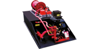
- Product Title: 1000 gallons Resupply Foam Trailer
- Product Details: CET fire Pumps manufacturers a variety of foam trailers from 150 to 2,000 gallons. These versatile trailers are ideal for use in Industrial, commercial, municipal and forestry environments. Foam trailers provide a very effective tool for airport fuel storage and power plant installations.
- Foam Trailer Title Left Comlumn: WHY DO YOU NEED FOAM?
- Foam Trailer Title Right Comlumn: GENERAL INFORMATION:
-
Foam Trailer Text Left Comlumn:
- Foam is needed for any fire or spill involving flammable or combustible solids or liquids
- Water will not float on hydrocarbon products such as gasoline or diesel fuel.
- Water used on a fire in a contained area may sink, runoff or overflow.
- Foam reduces toxic and flammable vapors given off by fuels.
-
Foam Trailer Text Right Comlumn:
- The following specifications are for a mobile foam resupply trailer of 1000 gallon capacity with accessories for use as a firefighting unit. The trailer is intended to be towed by a support vehicle, of adequate capacity, to the scene of a fire and/or various types of spills for the purpose of fire suppression support. A one person operation shall allow for the transfer of foam to the fire at the scene of major incidents.
- Product shall be completely brand new and of the best quality materials currently used in commercial practice for emergency vehicle fabrication. Materials that deteriorate when exposed to sunlight, extreme weather or operational conditions shall not be used or shall have a means of protection against such conditions that will not prevent compliance with performance standards. Protective coatings that chip, crack, or scale with age or extremes of climatic conditions or by exposure to heat or cold shall not used.
- The foam resupply trailer shall comply with all applicable Motor Carrier Safety Regulations, as it pertains to municipal emergency firefighting, concerning size, weight, brakes, lights, load rating and balance. Conformance must meet FMVSS#108, FMVSS#115, FMVSS#120, and FMVSS#125 as stated in FCR title 49 in effect at time of delivery.
- Weight shall be distributed as equally as practical over the axles and tires of the fully loaded vehicle. Fully loaded units that are unbalanced during stand alone operations or while being towed will not be accepted. Tires, wheels and axles shall be adequately sized for the load imposed by the in service weight of the completed trailer.
- The use of proven nonmetallic materials in lieu of metal is permitted if that use contributes to reduced weight, lower cost or less maintenance and there is no degradation in performance or increase in long term operations and maintenance costs.
- Foam resupply trailer must be constructed with lowest possible center of gravity when fully loaded with foam concentrate, tools and the appliances specified herein. Performance must be commensurate with smooth and safe highway and moderate off highway operation. Proper weight and balance configuration is essential.
-
foam-trailer-specifications-list:
I. TRAILER, TANK, AND COMPARTMENTS
A. TRAILER FRAME
GVWR – Gross vehicle weight rating shall not exceed 14000 pounds when fully loaded and equipped.
Size – Overall size of completed trailer (less packaging) not to exceed (approx..) 240” long, 90” wide, 70” high when measured from the ground surface.
Frame Weldment – The main trailer platform, cross members and a-frame hitch shall be constructed from rectangular tube steel and entirely MIG welded for maximum strength and torsional stiffness. Frame cross members shall be adequately spaced to support the load of the tank. A channel shaped rear bumper shall be included at the rear behind the tank to protect the rear of the tank. A .125 high bright aluminum diamond plate step area approximately 6” deep x 60” wide shall be provided for reaching the top of the foam tank. The A-Frame nose tubes shall under lap the main frame tubes for maximum strength in this area. A .125 thick aluminum plate shall be provided at the nose area of the trailer for the mounting of the transfer pump.Lashing Points – There shall be (4) lashing points which shall allow the trailer to be safety lashed to the deck of a trailer should the trailer need to be moved other than towing it. These lash points shall be made from ¾” diameter solid steel and bent to form a “V” and shall be positioned appropriately (2) each side of the main trailer frame tubes.
Fenders – Trailer fenders shall be heavy duty steel diamond plate type with center reinforcement supports. They shall support a firefighter in full turnout gear.
Axles – There shall be two axles, each with a rated capacity of 7,000 lbs. properly located under the trailer frame. Each wheel is to have individual functioning electric brake. Brakes shall have slack adjusters accessible from the back side of the backing plate. The bearings shall be sealed grease type. Hubs shall be cast type with pressed in wheel studs. The suspension shall meet or exceed the capacity of the axles and shall have slipper type springs. The main equalizer pivot point of the suspension shall have grease fittings.
Tires and Wheels – Tires to be ST235/80R16LRE. Wheels to be 16 x 6 rated for 3500 lbs. at 80 psi. and shall be matched to tires. Tow hook/Actuator – Military pintle ring type adjustable hitch shall be provided. Safety chains with slip hooks rated for 7000 lbs. each shall be provided at the front of the trailer. A break away line and trailer mounted battery shall be provided to activate brakes should the trailer become uncoupled from the tow vehicle.
“A” Frame Stand – One heavy duty 2,000 pound crank down detachable type stand to support the loaded trailer during stand alone trailer operations shall be provided.
Trailer Electrical Plug – A round 7 pin male connector shall be provided at the extreme front of the nose tube with at least a 30” cord extending beyond the front of the trailer. The matching female plug shall be provided with a wiring diagram for proper interface between the tow vehicle and the trailer. The main power cord shall terminate into a main sealed junction box located under the nose of the trailer. All wiring shall extend from this box as required. Wiring shall be heavy duty all weather type insulated sized properly for all applied loads and protected from damage by foam concentrate overflow and normal use. Electrical schematic to be provided for wiring tow vehicle. All wiring to be GXL cross linked with color coded function imprint every 4”. All wiring shall be in protected channels of metal conduit.
Tail, Clearance and License Plate Lights – The trailer lighting shall comply with FMVSS section 108 of FCR 49. There shall be two combination stop-tail-turn lights recess and shock mounted into a channel bumper at the rear of the trailer. Individual clearance lights on brackets shall mark the corners and rear of the trailer as required. A license plate light and bracket shall be located on the street side rear tapered plane of the fender.
Warning Lights – Two rear 7 x 8 red flashing LED lights shall be provided on the rear of the trailer. These lights shall be powered from the vehicles 4 way emergency flasher circuit.
Rear Tank Overlay – The rear of the tank below the hose bed shall be overlaid with 1/8” high bright aluminum diamond plate to protect the back of the tank from hose and couplings.
Work Lights – Two 2.5 x 6 clear lights shall be mounted (1) each side of the pump to illuminate all pump and piping controls for night operation. The switch for these lights shall be on the pump control panel. The power for these lights shall be from the main tail light circuit when the trailer is plugged into the tow vehicle.B. FAOM TANK
Size – Capacity for 1000 U.S. gallons. Low center of gravity type with adequate baffles.
Construction – The foam tank shall be constructed of ½” think polypropylene sheet stock with PolymarCo-PP resin. The material shall be a non-corrosive stress relived thermo-plastic, black in color and UV stabilized for maximum protection. The tank shall be designed to be an independent component of the completed vehicle. All joints shall be welded and tested for maximum weld integrity. The transverse partitions are to be fabricated from 3/8 polypropylene and shall be natural in color and shall extend from within 4” of the tank floor to the underside of the covers. The longitudinal partitions shall be fabricated from ½” polypropylene (black in color) and extend from the floor thru the covers to allow for positive welding and maximum integrity. All partitions shall be equipped with vent and flow holes to permit proper flow of foam and air within the tank under all conditions. All partitions interlock with each other and are fully welded to the sidewalls of the tank as well as to each other. The tank covers shall be of a flush design to eliminate trapping of water or foam on the top surface.
Fill Tower – A fill tower shall be constructed which will allow the tank to be filled from 5 gallon foam cans. This tower shall be configured to allow two cans to be poured simultaneously into the foam tank. The design shall let the main tank vent as well as positioning the 5 gallon cans to fully self draining. The tower shall have a hinged lid and a retaining devise to stop the lid from folding over on itself. A pressure vacuum vents shall be installed in this tower lid to eliminate air exchange unless foam is pumped into or out of the main tank or if thermal expansion or contraction of the liquid occurs. A label on the outside of the tower to read “FOAM CONCENTRATE ONLY”.
Sump
A sump shall be provided to trap any foreign items that may become trapped in the tank. The sump shall be fabricated from ½” copolymer sheet stock and shall be permanently welded to the bottom of the tank.
Sump Drain
The floor of the sump shall be fitted with drain outlet. A 2-1/2” port in the sump shall be piped to a 1-1/2” valve to allow the tank to be drained. The valve shall be labeled “DRAIN – FOAM CONCENTRATE”.
Gauge – A vertical 2” wide translucent section of the tank shall be provided near the pump operator’s position to accurately monitor foam level within the tank. Tanks utilizing electronic level devises will not be acceptable.C. COMPARTMENTS
Hose Compartments – There shall be two (2) cross lay type hose beds approximately 14” H x 12” W across the front of the tank. Each compartment shall have a minimum capacity of 200 feet of 1.75” double jacketed fire hose. These hose beds shall hold the hose to be used for foam concentrate transfer operations. Each cross lay shall be labeled “CROSS LAY – CONCENTRATE #1 AND CROSS LAY CONCENTRATE #2” respectively.
Tool/Adapter/Accessory/Compartments – There shall be one compartment on top of the foam tank immediately behind the cross lay beds on the street side constructed of polypropylene. The compartment shall be fitted with a bright aluminum diamond plate cover and equipped with a hold open devise and a draw type latch. A weather resistant seal shall be provided on the cover. Drain provisions to allow any water entering the compartment to drain out shall be provided.
Large Diameter Hose bed - A hose bed open to the rear of the trailer shall be provided on top of the tank. It shall be the entire top width of the tank and shall occupy approximately two thirds of the total tank top surface. The bed shall have 3 sides to form the walls. The side walls shall be capped with 1” OD tubes with a rear 3” radius to allow hose to pay out without damage. This hose bed area shall have a capacity of 1000 ft of 5” LDH or 1200 ft of 4” LDH.II. PUMP
A. Pump
There shall be a 150 GPM self-priming gasoline driven pump for on loading and off loading the foam concentrate. Pump to be cast iron with foam resistant internal components. Pump is to have an electric start with recoil back-up, gasoline driven, fuel tank and battery. A battery box shall be fabricated from ¼” co-polymer polypropylene sheet stock to hose battery. This box shall have a removable cover and shall have 5” x 5” vented side panel. The pump shall be mounted at front on the “A” frame portion of the trailer frame. A plastic isolator shall be installed under pump to eliminate contact of dissimilar metals. Provisions to manually fill the pump initially shall be provided. This shall be labeled “FILL TO PRIME”. A yellow warning label shall be placed near the pump start controls which reads. “DO NOT RUN ENGINE WITH PUMP DRY OR PUMP SEAL WILL BE DAMAGED. FILL PRIME PORT PRIOR TO STARTING”.
B. Pump Connections and Piping
The permanently mounted pump shall be capable of pumping foam concentrate from the tank or from 55 gallon drums. All piping shall be stainless steel or high pressure foam resistant hose. All concentrate valves shall be bronze body full flow with chrome plated brass ball with a nylon seat. Valves shall have lever type handles for rapid opening and closing.
NOTE : All plumbing shall be designed for easy maintenance and/or replacement using grooved couplings or mechanical couplings.
1. Provide one (1) 2” suction piping arrangement from the tank to the pump with a ¼ turn tank isolation valve mounted at the tank. There shall be a label to identify this valve as “TANK TO PUMP”
2. Provide one (1) 1.5” NST-M inlet on main tank to pump (suction) line to be used as an auxiliary suction port connection for a pick up tube device through the suction side of the pump. Also, provide cap and chain for the 1.5” inlet. This inlet shall be labeled “AUX. SUCTION”
3. Provide two (2) 1.5” gated concentrate outlets from discharge side of pump. Both shall be plumbed to the bottom of each of the two cross lay hose compartments for concentrate transfer operations. Each discharge shall terminate in a 1.5” 90° continuous type brass swivel device mounted below hose beds to facilitate left or right side deployment of foam supply hose without kinking from the pump. Each valve shall be labeled “CROSS LAY – CONCENTRATE #1 AND CROSS LAY CONCENTRATE #2”, respectively.4. Provide (1) gated concentrate outlet from the pump back to the tank to allow foam to be on loaded into the tank from the on board pump. The inlet connection within the tank shall extend straight downward to within 1” of the floor to reduce foam agitation while filling.
III. ACCESSORIES
Provide the following accessories for use with the foam resupply trailer:
A. Suction Hose
Provide one (1) approximately 72” long PVC 1.5” suction line with an 18” and a 40” PVC pipe pick up tube for drawing concentrate from 5 gallon cans or from 55 gallon barrels. This suction hose assembly shall also have a PVC 1-1/2” quarter turn ball valve located at the suction end of the hose to allow the pump operator to control foam flow into the pump while switching concentrate supply containers. Provisions shall be made to safely carry these items on the trailer.
B. Fill Nozzles
Provide two fill nozzles for the end of each of the concentrate hose bed hoses. Each fill nozzle shall consist of a 1-1/2” quarter turn PVC ball valve with a 1-1/2 NST-F swivel inlet x 1-1/2 NST-M outlet. These are to allow for direct bottom filling of foam tanks. Two 90 degree pipe extensions shall be included that are approximately 42” in length and have a 1-1/2” NST-F swivel inlet connection. These can be added to the fill valves for top filling of other foam tanks through there fill towers. Provisions shall be made to safely carry these items on the trailer.
C. Manuals/Instruction
Technical manuals, parts manuals, and repair manuals for all installed equipment and accessories shall be provided with the trailer. They shall include all maintenance recommendations and full operational information for each function that the trailer is designed to perform.
Wheel Chocks
One set of wheel chocks shall be provided to allow the trailer to operate as a stand alone unit. Provisions shall be made to safely carry these wheel chocks on the trailer.
IV. TREATING AND PAINTING
A. Painting
A proven urethane automotive paint system shall be used to prime and paint the foam resupply trailer and the tank. Prior to priming, the entire steel trailer frame weldment shall be sand blasted to remove all mill scale and oils. Then it is to be hand sanded and primed. Any areas of overlapping seams shall be caulked after priming and before finish top coat. A bottle of touch up paint matching the top coat color shall be provided. The paint finish shall be of an automotive type quality. The color is to be as follows :
COLOR _________________________ Paint color number _____________________B. Lettering
The trailer shall be lettered as directed below. (up to 80 2” or 3” letters are to be provided. Up to two 3” stripes may be specified. All lettering to be Scotchlite. )
Lettering sides of trailer ___________________________________________________
Striping sides of trailer _____________________________________________________ -
Foam trailer Drawing:


- Product Header Image: images/firepump/stroke-5.png
-
Product Image:

- Category Product: Foam Trailer
-
Pdf / Print file:
- Product Title: 500 Gallons Foam Trailer
- Product Details: CET fire Pumps manufacturers a variety of foam trailers from 150 to 2,000 gallons. These versatile trailers are ideal for use in Industrial, commercial, municipal and forestry environments. Foam trailers provide a very effective tool for airport fuel storage and power plant installations.
- Foam Trailer Title Left Comlumn: WHY DO YOU NEED FOAM?
- Foam Trailer Title Right Comlumn: TRAILER UNIT
-
Foam Trailer Text Left Comlumn:
- Foam is needed for any fire or spill involving flammable or combustible solids or liquids
- Water will not float on hydrocarbon products such as gasoline or diesel fuel.
- Water used on a fire in a contained area may sink, runoff or overflow.
- Foam reduces toxic and flammable vapors given off by fuels.
-
Foam Trailer Text Right Comlumn:
- Size: Not to exceed (approx.) 220” long, 96” wide, 80” high when measured from surface.
- Axles: Tandem 6,000 pounds axles are to be used on the trailer. Each wheel is to have an individual surge brake.
- Tires and Wheels: Minimum 8 14.5 LT 12 ply tires with a capacity of 2,790 lbs. each at 100 PSI. Wheels shall be 14.5 x 6 rated at 2,790 lbs. each.
- Tow Hook/Brake Actuator: 3” adjustable pintle type lynette ring. Safety chains rated 12,000 lbs. per pair shall be provided at the front of the trailer. A breakaway line must be provided to activate brakes should the trailer become uncoupled from the tow vehicle.
- Stands: Three heavy-duty 2,000 pound crank-down detachable type stands shall be mounted to provide support during stand alone trailer operations.
- Wheel Chock: A set of wheel chocks to be provided for stand-alone firefighting operations. They shall be mounted to the angled surfaces of the curbside fender.
- Lights: Dual 6” red (LED) flashing warning lights shall be mounted on the rear of the trailer and white platform work lights shall be mounted in the work area. D.O.T. standard brake lights and directional signals shall be provided.
- Wiring: Heavy duty all weather type insulated wire sized properly for all applied loads and protected from damage by foam concentrate overflow and normal use. All wiring shall originate from front trailer plug. An electrical schematic is to be provided for wiring tow vehicle.
- Work Platforms: There shall be one aluminum diamond plate platform on front A-frame of trailer (aft of hitch) and one aluminum plate platform shall be provided at the rear of the trailer for pump mounting.
- Gross Vehicular Weight (GVW): Shall not exceed 12,000 pounds.
-
foam-trailer-specifications-list:
FOAM TANK
Size: 500 gallon PolymarCo-PP propylene foam tank. Low center of gravity type with adequate baffles.
Gauge: Clear visual liquid level site gauge convenient to operator’s area at the rear and front of the trailer.
Fill Tower: 24” x 13” x 7” high tower with hinged liquid tight cover that will prevent foam concentrate from splashing out of the fill tank during movement and provides for reverse filling to control agitation.
Vent: pressure/vacuum vent shall be installed into the foam fill tower.
Drain: A 1.5” NST-F valved drain shall be plumbed off the sump. A cap and chain shall be provided. Outlet shall terminate behind wheel on street side of trailer.
COMPARTMENTS
Top Storage Area: A covered storage compartment no smaller than 14” x 16” x 67” shall be provided on top of the tank. Com partment walls shall be integrally welded to foam tank. A gasketed hinged aluminum diamond plate cover with a latch shall be provided.
Suction Hose Storage Area: An open compartment shall be provided for the storage of concentrate suction hoses and fittings.
FIRE ATTACK EQUIPMENT
Attack Hosebeds:
- Provide two (2) crosslay hosebeds approximately 16” W x 10” H x 67” L across the tank. The crosslay shall be capable of containing 200’ 1.75” DJ fire hose. The crosslay shall have a valved 0-1-3-6% 120 gpm educator. The educator shall be plumbed off a dual inlet 5” manifold with a 2” bronze body ¼ turn valve and shall terminate in the hosebed with a 90 degree continuous swivel with 1-1/2” NST-M hose threads.
- Provide a crosslay hosebed approximately 18” W x 10” H x 67” L across the tank behind the 1.75” crosslay hosebeds. The hosebed shall be capable of containing at least 300’ of 2.5” DJ firehose. The crosslay shall have a valved 0-1-3-6% 250 gpm educator with a 2.5” full flow valve and shall terminate in the hosebed with a NST-M 2.5” chicsan swivel.Foam Monitor: Provide a pre-piped demountable 1-3% 500-gpm self-educting foam monitor with matching ground base. The ground base shall have two clappered 2.5” inlets. The monitor shall be an Akron “Akrofoam” type with truck mount. Monitor tobe plumbed off 5” manifold with a 3” riser with a bronze body ¼ turn valve. The ground base shall be mounted to the rear deck of the trailer with the appropriate brackets.
Remote Proportioning: A matched 1-3% pre-plumbed matched jet-ratio shall be mount-piped of 5” water manifold with a 1.5” valve and a 1-1/2” NST cap.
5” Manifold: The 5” manifold shall terminate in a 5” NST adapter. The manifold shall be equipped with a 2.5” gated siamese with plugs and a 4” gated storz inlet valve. The manifold shall have a 4” liquid filled pressure gauge and a 3/8” brass drain.
Hosebed Covers: All hosebeds will have a snap on black vinyl hosebed cover.
PUMP
Pump: One (1) 35pm gas powered rotary gear pump set up for concentrate transfer is to be provided. Pump is to have electric start, integral fuel tank, battery, and recoil start back up. Pump is to be driven by gasoline engine. Pump battery to have weatherproof box with enclosed battery conditioner and weatherproof shoreline plug receptacle. An adjustable relief valve shall be provided. The return line shall be piped integrally to the front of the tank for maximum deaneation of foam.
Pump Connections and Piping: The permanently mounted pump shall be capable of pumping foam concentrate from the tank or from 55 gallon drums and supplying it to a remote location such as other foam consuming apparatus. NOTE: All pipes shall feature easy maintenance and/or replacement using Victaulic couplings. All concentrate piping shall be brass. All valves to be 2” full flow.
- Provide one (2) 2” suction pipe from the tank to the pump with a ¼ turn tank isolation valve mounted at the tank.
- Provide two (2) 1.5” NST inlets on main tank to pump (suction) line in order to use Aux. Pick up tube device through the pump. Also, provide plug and chain for the 1.5” inlets.
- Provide (2) 1-1/2” piped outlets from pump. One shall be plumbed to a valved 1.5” outlet and shall be furnished with a cap. The second one is to serve as a tank fill line from the pump. The pipe is to extend into and towards the tank bottom to limit foam agitation while filling. Each discharge shall have a 1-1/2” quarter turn on/off valve capable of convenient and rapid activation from the operator’s rear.
- The third discharge shall be plumbed through a chicsan swivel to a 100’ capacity 1.75” pre-connected hosebed to permit the rapid transfer of foam concentrate to other tanks or apparatus. The discharge shall have a 1-1/2” quarter turn on/off valve capable of convenient and rapid activation from the operator’s rear platform area.ACCESSORIES
Provide the following accessories for use with the foam resupply trailer :
- Two (2) each approximately 120” long PVC 1.5” suction line with a 40” pick up tube for pumping concentrate from 55 gallon barrels.
- One (1) each PVC 1.5 foam fill tube approximately 48” long with shut off valve. Inlet connection on fill tubes to be 1 ½” NST-F swivel type.
- Provide technical manuals, parts manuals, and repair manual for all installed equipment and accessories.OPERATIONAL ACCESSORIES
Generator package – The trailer shall have a mounted gas powered with a recoil start 2000 watt Honda generator pre-wired to two individually switched telescoping 500 watt floodlights.
Receiver Mount Combo Pintle Hook/Ball Hitch: Receiver Mount Combination Ball Hitch with integral receiver shank. Fits 2” square receivers, 2-5/16” ball. Capacity for Pintle Hook is 12,000 lbs. maximum gross trailer weight. Capacity for Ball Hitch is 7,000 lbs. maximum gross trailer weight. Single piece drop forged lower jaw is designed with an integral shank to fit 2” receiver tubes. This design eliminates the need for a more costly assembly consisting of ball hitch, pintle mount and mounting hardware. Finished with black powder coat for superior durability and corrosion resistance.
TREATING AND PAINTING
Painting and Lettering: A proven paint system shall be used to prime and paint both the foam resupply trailer and the tank with appropriate color paint and shall be of an automotive quality finish. Letters on each side and not to exceed 26 letters (for example “Fire District 6 # ____”. All lettering shall be constructed of high performance vinyl with a minimum of a 5-year warranty of the material and will be 4” gold with black shadowing. A 4” white scotchlite stripe with two ¾” white stripes shall encircle the trailer. The two ¾” stripes will be placed ¾” from the top and bottom of the 4” stripe to create a white/red/white/red/white appearance. The trailer shall be red.
Labels: All devices will have fixed weatherproof labels or tags. Instructional plates will be mounted directly adjacent to operational controls.
TRAINING
Upon delivery of the trailer the supplier will provide a training session for up to 20 persons at a location to be determined by the purchaser. In the initial training session all aspects of operation and maintenance shall be presented or addressed. The supplier shall support the development of a training program for use by the end use departments.
-
Foam trailer Drawing:


- Product Header Image: images/firepump/stroke-5.png
-
Product Image:

- Category Product: Foam Trailer
-
Pdf / Print file:
- Product Title: Dual Tote Foam Trailer
- Product Details: CET fire Pumps manufacturers a variety of foam trailers from 150 to 2,000 gallons. These versatile trailers are ideal for use in Industrial, commercial, municipal and forestry environments. Foam trailers provide a very effective tool for airport fuel storage and power plant installations.
- Foam Trailer Title Left Comlumn: WHY DO YOU NEED FOAM?
- Foam Trailer Title Right Comlumn: TRAILER SPECIFICATIONS
-
Foam Trailer Text Left Comlumn:
CET fire Pumps manufacturers a variety of foam trailers from 150 to 2,000 gallons. These versatile trailers are ideal for use in Industrial, commercial, municipal and forestry environments.
Foam trailers provide a very effective tool for airport fuel storage and power plant installations.
- Foam is needed for any fire or spill involving flammable or combustible solids or liquids
- Water will not float on hydrocarbon products such as gasoline or diesel fuel.
- Water used on a fire in a contained area may sink, runoff or overflow.
- Foam reduces toxic and flammable vapors given off by fuels.
CALL YOUR CET DEALER, REGIONAL MANAGER, OR OUR OFFICE DIRECTLY FOR MORE INFORMATION.
-
Foam Trailer Text Right Comlumn:
Unit is to be installed on a double axle trailer:
- Heavy duty steel trailer w/steel floor
- Trailer to be painted red
- Plate form trailer dimension to be 11’ long x 5’ between the fenders
- Tandem axles : 7,000 lbs
- Electric brake
- 7 Pins trailer plug
- Sealed DOT LED lights
- 2-5/16” ball attachment assembly
- Front jack w/7,000 lbs. capacity
- Two (2) rear 5,000 lbs. downrigger stabilizers
- Two (2) Steps, one each side, located on the front of each fender
-
foam-trailer-specifications-list:
STRIPPING
Side, Front and Rear DOT stripping shall be applied on each side of the trailer. DOT stripping will be red and white reflective stripes.
FOAM TOTE TANKS
Two (2) foam tote tanks shall contain 265 (or 330) gallons of foam concentrate each, measuring 48” x 40” x 46” high each and shall be UV protected. Each tote shall have two (2) opening: one (1) 6” on the top with cap and one (1) 2” ball valve outlet at the bottom. Each tote shall have a pressure/vacuum vent on the top. Each tote shall be protected by a tubular steel grid. Each tote shall be DOT approved.
The trailer shall have a quick and safety tote connector to replace empty tote by full tote.
Two (2) 265 (or 330) gallon bulk container tote tanks shall be supplied empty.
FOAM PIPING
There shall have a 1-1/2” stainless steel rigid tube from the totes to the front of the trailer. Each tote shall be connected to the 1-1/2” pipe with a flexible hose and a 2” Cam-lock fitting for an easy connection. A 1-1/2” Fire Type quarter turn swing-out valve shall be installed at the front of the stainless steel tube.
4” WATER MANIFOLD
All piping shall be stainless steel piping, painted red. The water inlet piping shall consist of a 4» manifold tube. The piping is secured on the front side of the platform of the trailer.
The inlet overboard shall have two (2) 4” Storz connections with cap and chain, one (1) on each end of the manifold.
One (1) 4” pressure gauge shall be tapped into the manifold tube and shall be easily readable from ground.
One (1) 3/8” brass drain shall be tapped into the manifold.
TRAILER MOUNTED MONITOR
One (1) monitor shall be supplied and installed centered of the water manifold.
The monitor shall be provided with tiller bar control and manual friction brake operation and be able to travel 360° horizontal and 150° vertical. The full 3” waterway delivers efficient flows up to 1250 gpm.
One (1) self-educting nozzle designed for educting foam at flow rates up to 1000 gpm shall be provided and installed on the monitor. The nozzle shall have spring loaded baffle that allow flow setting selection of 350, 500, 750 or 1000 gpm with a simple push and turn of the baflle head. The nozzle shall have an adjustable metering head with pick up rates 1% & 3% plus 6% for 350 & 500 gpm and 1% & 3% for 750 & 1000 gpm.
The monitor shall be gated with a 3” full flow Fire Type quarter turn swing-out valve off the water manifold.
The plumbing shall be 3” stainless steel.
TWO (2) HOSE TRAYS
Two (2) hose trays made from 0.100” bright aluminum diamond plate, dimensions are 48” Long X 8” High X 12” Wide, shall be provided with canvas and net. Each compartment shall be capable of holding 200’ of 1-3/4” hoses.
The compartments shall be installed over the wheel well, one (1) on the left (driver) side and one (1) right (passenger) side. The compartments shall be secured properly to the top of the wheel well.
GENERAL WARRANTY
CET warrants to the original purchaser that CET will, at its election, either replace or repair any part of the new equipment sold to the purchaser hereunder which has been given no abnormal use; and which has received proper maintenance; and which is determined by CET to be defective in material or workmanship; and which has, within one (1) year after delivery to the purchaser be returned at the purchaser’s expense, with transportation charges prepaid, to CET factory OR which has, within one (1) year after delivery to the purchaser, been pre-approved by CET for a third-party to perform the work. All problems shall be reported to CET in writing and damaged parts shall be returned to CET.
EXCLUSIONS FROM WARRANTY
- CET incurs no liability under this warranty or otherwise for parts, accessories or components not manufactured by it, but purchased for assembly into the equipment, but CET will assign to the Purchaser whatever warranty rights are extended by the supplier of such part, accessory or component
- CET incurs no liability under this warranty or otherwise, for equipment which has been abused, altered or improperly maintained, or for equipment which has been returned for inspection or repair more than ten (10) days after defect complained of has been or should have been discovered by the Purchaser, or Equipment which is operated after the defect has been discovered.
- CET incurs no liability for alteration or repairs unless the Purchaser first receives CET / written consent or approval. CET will not be responsible for work or repairs made or done by others.
- CET incurs no liability for design alterations, parts, accessories or components which are not standard but are specified by the Purchaser for incorporation into the equipment.
INTERPRETATION
CET shall not be liable for transportation charges either in shipment to or by it and shall not be liable for loss of use, or consequential damage of any kind in connection with the sales, alteration, repair or replacement of any equipment or part thereof. Liability under this warranty is limited to replacement or repair and in any event shall not exceed the purchase price paid. This warranty is not transferable by the Purchaser. CET reserves the right to make changes in design or add any improvements to the Equipment at any time without incurring any obligation to install or modify same on other equipment previously supplied. There are no other warranties, conditions or representations, expressed or implied, except the above.
MANUFACTURER’S DISCRETION
Materials, parts, or procedures used are subject to change at manufacturer’s discretion at any time to provide equal or better product.
-
Foam trailer Drawing:


- Product Header Image: images/firepump/stroke-5.png
-
Product Image:

- Category Product: Foam Trailer
-
Pdf / Print file:
- Product Title: 1000 gallons Foam Trailer
- Product Details: CET fire Pumps manufacturers a variety of foam trailers from 150 to 2,000 gallons. These versatile trailers are ideal for use in Industrial, commercial, municipal and forestry environments. Foam trailers provide a very effective tool for airport fuel storage and power plant installations.
- Foam Trailer Title Left Comlumn: WHY DO YOU NEED FOAM?
- Foam Trailer Title Right Comlumn: TRAILER SPECIFICATIONS
-
Foam Trailer Text Left Comlumn:
CET fire Pumps manufacturers a variety of foam trailers from 150 to 2,000 gallons. These versatile trailers are ideal for use in Industrial, commercial, municipal and forestry environments.
Foam trailers provide a very effective tool for airport fuel storage and power plant installations.
- Foam is needed for any fire or spill involving flammable or combustible solids or liquids
- Water will not float on hydrocarbon products such as gasoline or diesel fuel.
- Water used on a fire in a contained area may sink, runoff or overflow.
- Foam reduces toxic and flammable vapors given off by fuels.
CALL YOUR CET DEALER, REGIONAL MANAGER, OR OUR OFFICE DIRECTLY FOR MORE INFORMATION.
-
Foam Trailer Text Right Comlumn:
Unit is to be installed on a double axle trailer:
- Heavy Duty Steel trailer w/steel floor
- Trailer to be red
- Plate form trailer dimension to be 19’ long x 6’ between the two fenders
- Rear tandem axles : 16,000 lb
- Each wheel shall have an electric brake
- 7 Pins trailer plug
- Sealed DOT lights
- 3” adjustable pintle attachment assembly
- 12,000 lb. Safety Chains with Break-Away wire for electric breaks.
- Front jack w/12,000# capacity
- Two (2) rear downrigger stabilizers
- Four (4) 16 in all seasons tires
- One (1) Spare tire w/rim installed on the trailer
- Two (2) Steps, one each side, located on the front of each fender
- Wheel Chocks shall be mounted on street side fender
-
foam-trailer-specifications-list:
STRIPPING & LETTERING
Side, Front and Rear DOT stripping shall be applied on each side of the trailer. DOT stripping will be red and white reflective stripes.
Two (2) smooth aluminum plates shall be installed, one (1) each side of the dunage compartment in matter to applied desired Fire Department Lettering. Lettering supplied and installed by CET.
REAR CHEVRON
On the back of the trailer shall be a red / yellow NFPA approved rear chevron.
WORK PLATFORM
There shall be one aluminum diamond plate platform on front A-frame of trailer (aft of hitch) and aluminum diamond plate platform shall be provided at the front and the rear of the foam tank.
WHEEL CHOCKS
Medium Kochek Wheel Chocks with storage bracket installed on the street side of the trailer for quick deployment.
FOAM TANK(S)
There shall be two (2) foam tanks integrated in the same tank on the trailer. Each foam tank shall be constructed of PT2E polypropylene sheet. Each Foam tank shall be welded with Heavy Duty extruded joint. The material shall be of a certified, high quality, non-corrosive, stress relieved thermo plastic, black in color with a textured finish, and UV stabilized for maximum protection. The unit shall incorporate transverse partitions manufactured for 3/8’’ PT2E polypropylene which shall interlock with a series of longitudinal partitions constructed of 3/8’’ PT2E polypropylene. All swash partitions shall be so designed to allow for maximum water/foam and air flow between compartments and are fully welded to each other as well as to the inside of the tank.
- There shall be a standard 2” in width, 70% transparent sight gauge on both foam tanks.
- There shall be a gauge on the front of both tanks.
FILL TOWER AND TANK COVER
Each tank shall be equipped with one (1) fill tower with a combination vent/overflow and manual fill tower. The fill towers shall be 24’’ x 13’’ x 7’’ high rectangular drop-on type cover. The covers shall be fastened to the tower with a teather to prevent loss. The towers shall be located in the passenger and driver side rear corner of the tank. The tank cover shall be constructed of 1/2’’ thick PT2E polypropylene, black in color, UV stabilized.
Tank will be baffles in accordance with NFPA bulletin 1901 requirements, latest version.
Each fill tower shall be labeled respectively for each Foam Tank 1 and Foam Tank 2.
Each tank shall not be painted and be black in color.
There shall be a 2” vent installed each fill tower.
TANK CAPACITY
Each tank shall have a capacity of 500 U.S. gallons. The tanks shall be covered by the ALL OUT No Fault Life Time Warranty.
SUMP
The floor of the tank shall be manufactured from 3/4’’ PT2E polypropylene. There shall be one (1) sump on each tank. The sump shall be 10” x10” x 3” under the floor. Each sump shall have 1-1/2” NPT female drain.
TANK OUTLETS
There shall be two (2) outlets on each tank located in the same horizontal plane at the backward wall of the tank. One outlet shall come with 2-1/2’’ female NPT tank to pump suction fitting.
The other shall be a 1.5” NPT for tank fill(s). Both shall come with 1-1/2’’ female NPT tank fill fitting with flow deflector.
TANK MOUNTING BLOCKS
The cover shall incorporate two (2) booster reel mounting blocks that shall be to accommodate two (2) each sliding nut fasteners. These 3’’ large mounting blocks shall be welded to the covers forward and backward of welded compartments.
MOUNTING
The foam tank shall not be welded or otherwise permanently secured to other components, except the top storage compartments.
1.5’’ TANK DRAIN(S)
Two (2) 1.5” drains shall be plumbed off, one (1) on each sump. The valves shall be furnished with a 1.5’’ NST swivel adaptor with a 1.5 NH plug and chain. Each drain shall terminate behind of the wheels.
TOP STORAGE COMPARTMENT
There shall be a compartment made of ½” polypropylene sheet, internal dimensions are 69-1/2” Long X 15” High X 17-1/2” Wide.
The compartment shall be welded on the top of the foam tanks. There shall be a hinged aluminum lid sealed with a gasket. This compartment shall be capable of storing loose equipment, and suction hoses. The compartment floor shall be covered with black Turtle Tiles.
5 GALLON FOAM PAILS STORAGE COMPARTMENT
There shall be an additional storage compartment made from ½” polypropylene sheet, dimensions 69-1/2” Long X 15” High X 54-3/4” Wide. This compartment shall be capable of holding a minimum of 20 – 5 gallon cans of foam. The compartment floor shall be covered with black Turtle Tiles.
WATER MANIFOLD
All piping shall be stainless steel piping, painted red. The inlet piping shall consist of a 6’’ manifold tube. The inlet overboard shall have two (2) 5” Chrome NST adaptor connections with chrome cap. There shall be two (2) 5” X 2.5” Siamese Gated Wye and shipped loose. All threads shall be NST Thread.
One (1) pressure gauge shall be tapped into the 6” manifold tube and shall be easily readable from ground. This gauge shall be a 4” master gauge liquid filled and 0 – 300 psi.
There shall be two (2) drain valves for flushing and maintenance purposes.
TRAILER MOUNTED MONITOR
One (1) Akron Apollo monitor #3416 shall be supplied and installed centered of the master discharge manifold. The monitor shall have a handwheel controlled vertical travel. Monitor ground base shall be included and installed on the rear passenger of the trailer. The ground base shall have a 4” NST threaded inlet.
The monitor shall include one (1) self-educting master stream nozzle designed for educting foam at flow rates up to 750 gpm. Model to be #4475 Pyrolite Akrofoam Akron Nozzle with spring loaded baffle that allow flow setting selection of 350, 500, 750 gpm.
The educting foam nozzle shall be able to flow foam from either foam tank.
The monitor shall be plumbed by 3” stainless steel tube with a 3” Fire Type quarter turn swing-out valve.
FOUR (4) PRE-CONNECT CROSS LAYS
Four (4) pre-connect cross lays made from polypropylene sheet shall be supplied and installed on top of the front of foam tanks. Hose trays shall have a black vinyl snap canvas cover and side nets. Each area shall be designed to prevent the accumulation of water and allow for ventilation to aid in drying hose in the storage area. Black Turtle Tiles to be installed and bolted on the floor.
Two (2) cross lays shall be capable of storing 200’ of 2” jacket fire hose. The dimensions of these two (2) cross lays shall be 9” Wide X 10” High X 72” Long.
There shall be a 2.0’’ full flow valve piped from the 6’’ suction manifold to each cross lay. Each valve shall be an Fire Grade, quarter turn swing out valve with a chromed handle and be connected to each cross lay by 1-1/2” high pressure flexible plumbing.
Each cross lay shall have 125 GPM flow Akron model #3125 foam eductor allow foam from either tank.
Each cross lay shall have a 1.5” pre-connect 90 deg. swivel elbow.
Each cross lay shall have a 2.5” Liquid filled gauge 0 - 300 psi.
Two (2) cross lays shall be capable of storing 200’ X 2.5” jacket fire hose. The dimensions of these two (2) cross lays shall be 11” Wide X 10” High X 72” Long.
There shall be a 2.5’’ full flow valve piped from the 6’’ suction manifold to each cross lay. Each valve shall be an Fire Grade, quarter turn swing out valve with a chromed handle and be connected to each cross lay by 2-1/2” high pressure flexible plumbing.
Each cross lay shall have 250 GPM flow Akron Model #3250 foam educator allow foam from either tank.
Each cross lay shall have a 2.5” pre-connect 90 deg. swivel elbow. Each cross lay shall have a 2.5” Liquid filled gauge 0 - 300 psi.
Akron Municipal Eductors feature a large, easy to read, and removable metering dial with infinite settings between 0% and 6%. Detents at 1⁄4, 1⁄2, 1, 3 and 6%. The Eductors are rated to flow at 200 psi (14 bar) inlet pressure and work well with nozzles rated at 75 and 100 psi (5 and 7 bar).
REMOTE JRC DISCHARGE CONNECTION
A matched pre-plumbed matched jet-ratio controller shall be piped off the 6’’ water manifold with a 1.5’’ valve and a chrome cap. The JRC discharge connection shall have 95 GPM flow Akron Model #3095 foam eductor allow foam from either tank. The discharge shall have a 2.5’’ liquid filled 0-300 psi pressure gauge.
TRANSFER PUMP, 11HP HONDA ROTARY GEAR GORMAN RUPP PUMP
The pump shall be a CET 11hpHonda rotary gear Gorman pump and shall be permanently mounted on that rear of the trailer. The pump shall be capable of flowing 50 GPM at 50 PSI.
- Size: 2’’ x 2’’ (51 mm x 51 mm) NPT - Female.
- Casing: Aluminum,open type,
- Two Vane Impeller: Ductile Iron
- Replaceable Wear Plate: Carbon Steel. Intermediate
- Bracket: Gray iron.
- Seal: Type 31 Mechanical Self Lubricated, Silicon Carbide Rotating and Stationary Faces. Fluorocarbon Elastomers (DuPont Vitone or Equivalent). Stainless Steel No. 18-8 Cage and
- Spring. Flap Valve: Buna-N w/Nylon Reinforcement;
- Flange: Aluminum.
TRANSFER PUMP ENGINE
The pump shall be driven by a single cylinder, gasoline engine powered, 11 horsepower at 3600 rpm. The engine shall be air cooled, 12 volt electric start and recoil rope starter as a back up system.
The engine shall be fuelled from a 6 quarts (6.5 liter) integrated gas tank. The engine shall have his own battery.
The battery shall have a weatherproof box with battery conditioner.
TRANSFER PUMP CONTROLS
A control panel shall be the standard Honda control panel supplied and installed on the pump.
TRANSFER PUMP SUCTION PIPING
All piping shall be stainless steel piping, painted red. The suction piping shall consist of a 2.5’’ tank to pump line for each foam tank with a 2.5’’ flexible rubber hump hose to minimize flex and vibration between the pump and the tank.
RIGID PIPING SHALL NOT BE ACCEPTABLE
Between the tank and the pump there shall be two (2) 2.0’’ Fire Type, quarter turn swing out valve, one (1) for each tank with a handle. Each valve shall remain open to pump from the tank.
The pipe shall have a tee into the suction side of the pump, and shall continue to the rear of the truck for overboard suction. The overboard suction connection shall have a 2.0’’ Fire Type, quarter turn swing out valve with a handle and 2.0” cam lock fitting.
To draft, the tank to pump valve shall be closed, a suction hose connected to the overboard suction connection and placed in a static foam supply.
TRANSFER PUMP DISCHARGE MANIFOLD
All piping shall be stainless steel piping or high pressure flexible hose. A 2.5’’ X 2.5’’ square stainless steel manifold shall be piped directly to the discharge outlet of the pump. Attached to this discharge manifold, by means of welded stainless steel pipe nipples, shall be all the discharge valves. All piping shall be painted red to match the pump.
There shall be a 2.0’’ valve piped from the transfer pump discharge manifold to each tank fill inlet. The valves shall be a Fire Type, quarter turn swing out valve with a handle and shall be connected to the each tank by 1.5’’ high pressure flexible hose. These discharges shall be designed to refill each tank in the most efficient manner without foam agitation. There shall be a 2.0” valve piped from the pump discharge as a service line and shall be furnished with a 2.5’’ NST cap and chain.
DISCHARGE TO BOOSTER REEL
There shall be a 1’’ valve piped from the discharge manifold to the booster reel. The valve shall be an industrial quarter turn valve handle and 1’’ NPT threads, and shall be connected to the reel by 1’’ high pressure flexible hose.
ELECTRIC BOOSTER REEL
One (1) 12v electric rewind booster reel capable of handling 100’ of 1’’ diameter booster hose. The reel shall have a push button rewind control and a backup geared crank rewind handle. The reel shall be equipped with a 1’’ NPT 90 degree swivel inlet, and a 1’’ NST outlet riser. The reel shall be manufactured of steel and shall be primed and painted red. Reel to be installed on the rear center between the foam fill towers, facing each side. 100’ of 1” Rubber booster hose shall be supplied and installed.
BOOSTER REEL ROLLERS
One set of high mounted roller and spool assemblies shall be furnished and installed. The high mount rollers shall allow hose to be deployed off either side of the trailer.
TRANSFER PUMP ACCESSORIES
One (1) 120’’ long translucent 2’’ suction line with a cam-lock 2’’ NST-M at one (1) end and a cam-lock 2’’ NST-F on the other end shall be provided.
One (1) 40’’ pick up tube and one (1) 18’’ pick up tube for pumping concentrate from 55 gallon barrels or 5 gallon pails shall be provided. One (1) PVC 1.5’’ shut off valve with a 90 degree PVC elbow with 2” cam-lock male at the end shall be provided on each pick up tube.
PORTABLE GENERATOR & LIGHTS
Generator package - The trailer shall have a mounted but removable gas powered generator with a recoil start 5000 watt EB5000 X2C2 Honda generator at the rear of the trailer, over the transfer pump. The generator shall have a fitted red vinyl cover. The generator shall have two 50’ 12-3 extension cords.
The generator shall have two telescopic scene lights model FRC OPA-642-S50-ON 500 watt tripod lights mounted in a way as they will be removable.
WARNING LIGHTS
There shall be four (4) 700 series Whelen super LED 3” X 7” red flashing emergency lights installed on the trailer. Two (2) shall be located on the rear bumper of the trailer red in color and two (2) shall be located on each fender, one (1) on the driver’s side and one on the passenger’s side. The lights shall be wired to the battery of the pump with a control switch located on the pump control panel labeled “Warning Lights”. There shall be a battery charger installed and wired to the battery of the pump. This charger shall charge the battery from the auxiliary port on the 7 way wiring plug when connected to the vehicle trailer lighting system.
TESTING
The trailer and all products shall be tested after the pump and all its associated piping and equipment have been installed on the fire apparatus. The tests shall be conducted at the manufacturer’s approved facility. The testing shall include at least the pumping tests, the priming device test, the vacuum test. The water tank-to-pump flow test and the piping integrity test.
GENERAL WARRANTY
CET warrants to the original purchaser that CET will, at its election, either replace or repair any part of the new equipment sold to the purchaser hereunder which has been given no abnormal use; and which has received proper maintenance; and which is determined by CET to be defective in material or workmanship; and which has, within one (1) year after delivery to the purchaser be returned at the purchaser’s expense, with transportation charges prepaid, to CET factory OR which has, within one (1) year after delivery to the purchaser, been pre-approved by CET for a third-party to perform the work. All problems shall be reported to CET in writing and damaged parts shall be returned to CET.
EXCLUSIONS FROM WARRANTY
- CET incurs no liability under this warranty or otherwise for parts, accessories or components not manufactured by it, but purchased for assembly into the equipment, but CET will assign to the Purchaser whatever warranty rights are extended by the supplier of such part, accessory or component
- CET incurs no liability under this warranty or otherwise, for equipment which has been abused, altered or improperly maintained, or for equipment which has been returned for inspection or repair more than ten (10) days after defect complained of has been or should have been discovered by the Purchaser, or Equipment which is operated after the defect has been discovered.
- CET incurs no liability for alteration or repairs unless the Purchaser first receives CET / written consent or approval. CET will not be responsible for work or repairs made or done by others.
- CET incurs no liability for design alterations, parts, accessories or components which are not standard but are specified by the Purchaser for incorporation into the equipment.
INTERPRETATION
CET shall not be liable for transportation charges either in shipment to or by it and shall not be liable for loss of use, or consequential damage of any kind in connection with the sales, alteration, repair or replacement of any equipment or part thereof. Liability under this warranty is limited to replacement or repair and in any event shall not exceed the purchase price paid. This warranty is not transferable by the Purchaser. CET reserves the right to make changes in design or add any improvements to the Equipment at any time without incurring any obligation to install or modify same on other equipment previously supplied.
There are no other warranties, conditions or representations, expressed or implied, except the above.
CET FOAM / WATER TANK WARRANTY LIFETIME
CET Fire Pumps, Mfg. warrants each CET water and/or foam tank to be from manufacturing defects in material and workmanship for the service life of the original vehicle. Every CET tank shall be thoroughly inspected and tested for leaks before leaving our facility and must be installed in accordance with the CET Fire Pumps, Mfg. installation guidelines.
CET will repair or, at its option, replace the tank with a new tank. CET will cover customary and reasonable costs to remove and install the tank. This warranty will not cover the tanks that have been improperly installed, misused, or abused. The serial number must not have been altered, defaced or removed. CET will not cover any unauthorized third party repairs or alterations. Any of these actions may void the warranty.
There are no warranties, expressed or implied, which extend beyond the description of the face, hereof. There is no express or implied warranty of merchantability or a warranty of fitness for a particular purpose. Additionally, this warranty is in lieu of all other obligations or liabilities on the part of CET Fire Pumps, Mfg. This warranty contains the entire warranty. It is the sole warranty and price agreements or representation, whether oral or written, are either merged herein or expressly canceled. CET Fire Pumps, Mfg. neither authorizes any person supposing to act on its behalf to change, nor assume for it, any warranty or liability concerning its product. In no event will CET Fire Pumps, Mfg. be liable for an amount in excess of the currently published retail price plus installation and removal cost of the tank, for any loss or damage, whether direct or indirect, incidental, consequential, or otherwise arising out of failure of its product.
This warranty gives you the specific legal rights, and you may also have other rights which vary from state to state. Some states do not allow exclusion or limitation of incidental or consequential damage, so the above limitation or exclusion may not apply to you. Since some states do not allow limitations on the length of an implied warranty, the above limitation may not apply to you.
The warranty is transferable within the United States and Canada at the discretion of CET Fire Pumps, Mfg. by notifying CET Fire Pumps, Mfg. within thirty (30) days of the vehicle transfer date. At that time, CET will, at it discretion, provide a transfer of ownership form.
MANUFACTURER’S DISCRETION
Materials, parts, or procedures used are subject to change at manufacturer’s discretion at any time to provide equal or better products.
-
Foam trailer Drawing:


- Product Header Image: images/firepump/stroke-5.png
-
Product Image:

- Category Product: Foam Trailer
-
Pdf / Print file:
- Product Title: Single Tote Foam Trailer
- Product Details: CET fire Pumps manufacturers a variety of foam trailers from 150 to 2,000 gallons. These versatile trailers are ideal for use in Industrial, commercial, municipal and forestry environments. Foam trailers provide a very effective tool for airport fuel storage and power plant installations.
- Foam Trailer Title Left Comlumn: WHY DO YOU NEED FOAM?
- Foam Trailer Title Right Comlumn: TRAILER
-
Foam Trailer Text Left Comlumn:
CET fire Pumps manufacturers a variety of foam trailers from 150 to 2,000 gallons. These versatile trailers are ideal for use in Industrial, commercial, municipal and forestry environments. Foam trailers provide a very effective tool for airport fuel storage and power plant installations.
Foam is needed for any fire or spill involving flammable or combustible solids or liquids
- Water will not float on hydrocarbon products such as gasoline or diesel fuel.
- Water used on a fire in a contained area may sink, runoff or overflow.
- Foam reduces toxic and flammable vapors given off by fuels.
CALL YOUR CET DEALER, REGIONAL MANAGER, OR OUR OFFICE DIRECTLY FOR MORE INFORMATION.
-
Foam Trailer Text Right Comlumn:
Unit is to be installed on a double axle trailer.
- Heavy duty steel trailer w/steel floor
- Trailer to be painted red
- Plate form trailer dimension to be 8’ long x 4’ between the fenders
- Tandem axles : 7,000 lbs
- Electric brake
- 7 Pins trailer plug
- Sealed DOT LED lights
- 2-5/16” ball attachment assembly
- Front jack w/7,000 lbs. capacity
- Two (2) rear 5 000 lbs. swivel downrigger stabilizers
- Two (2) Steps, one each side, located on the front of each fender
-
foam-trailer-specifications-list:
STRIPPING
Side, Front and Rear DOT stripping shall be applied on each side of the trailer. DOT stripping will be red and white reflective stripes.
FOAM TOTE
The foam tote tank shall contain 265 (or 330) gallons of foam concentrate, measuring 48” x 40” x 46” high and shall be UV protected. The tote shall have two (2) opening: one (1) 6” on the top with cap and one (1) 2” ball valve outlet at the bottom. The tote shall have a pressure/vacuum vent on the top. The tote shall be protected by a tubular steel grid. The tote shall be DOT approved. The trailer shall have a quick and safety tote connector to replace empty tote by full tote. One (1) 265 (or 330) gallon bulk container tote shall be supplied empty.
4” WATER MANIFOLD
All piping shall be stainless steel piping, painted red. The water inlet piping shall consist of a 4» manifold tube. The piping is secured on the front side of the platform of the trailer. The inlet overboard shall have two (2) 4” Storz connections with cap and chain, one (1) on each end of the manifold. One (1) 4” pressure gauge shall be tapped into the manifold tube and shall be easily readable from ground. One (1) 3/8” brass drain shall be tapped into the manifold.
TRAILER MOUNTED MONITOR
One (1) monitor shall be supplied and installed centered of the water manifold. The monitor shall be provided with tiller bar control and manual friction brake operation and be able to travel 360° horizontal and 150° vertical. The full 3” waterway delivers efficient flows up to 1250 gpm. One (1) self-educting nozzle designed for educting foam at flow rates up to 1000 gpm shall be provided and installed on the monitor. The nozzle shall have spring loaded baffle that allow flow setting selection of 350, 500, 750 or 1000 gpm with a simple push and turn of the baflle head. The nozzle shall have an adjustable metering head with pick up rates 1% & 3% plus 6% for 350 & 500 gpm and 1% & 3% for 750 & 1000 gpm. The monitor shall be gated with a 3” full flow Fire Type quarter turn swing-out valve off the water manifold. The plumbing shall be 3” stainless steel.
TWO (2) HOSE TRAYS
Two (2) hose trays made from 0.100” bright aluminum diamond plate, dimensions are 48” Long X 8” High X 12” Wide, shall be provided with canvas and net. Each compartment shall be capable of holding 200’ of 1-3/4” hoses. The compartments shall be installed over the wheel well, one (1) on the left (driver) side and one (1) right (passenger) side. The compartments shall be secured properly to the top of the wheel well.
GENERAL WARRANTY
CET warrants to the original purchaser that CET will, at its election, either replace or repair any part of the new equipment sold to the purchaser hereunder which has been given no abnormal use; and which has received proper maintenance; and which is determined by CET to be defective in material or workmanship; and which has, within one (1) year after delivery to the purchaser be returned at the purchaser’s expense, with transportation charges prepaid, to CET factory OR which has, within one (1) year after delivery to the purchaser, been pre-approved by CET for a third-party to perform the work. All problems shall be reported to CET in writing and damaged parts shall be returned to CET.
EXCLUSIONS FROM WARRANTY
- CET incurs no liability under this warranty or otherwise for parts, accessories or components not manufactured by it, but purchased for assembly into the equipment, but CET will assign to the Purchaser whatever warranty rights are extended by the supplier of such part, accessory or component
- CET incurs no liability under this warranty or otherwise, for equipment which has been abused, altered or improperly maintained, or for equipment which has been returned for inspection or repair more than ten (10) days after defect complained of has been or should have been discovered by the Purchaser, or Equipment which is operated after the defect has been discovered
- CET incurs no liability for alteration or repairs unless the Purchaser first receives CET / written consent or approval. CET will not be responsible for work or repairs made or done by others.
- CET incurs no liability for design alterations, parts, accessories or components which are not standard but are specified by the Purchaser for incorporation into the equipment
INTERPRETATION
CET shall not be liable for transportation charges either in shipment to or by it and shall not be liable for loss of use, or consequential damage of any kind in connection with the sales, alteration, repair or replacement of any equipment or part thereof. Liability under this warranty is limited to replacement or repair and in any event shall not exceed the purchase price paid. This warranty is not transferable by the Purchaser. CET reserves the right to make changes in design or add any improvements to the Equipment at any time without incurring any obligation to install or modify same on other equipment previously supplied. There are no other warranties, conditions or representations, expressed or implied, except the above.
MANUFACTURER’S DISCRETION
Materials, parts, or procedures used are subject to change at manufacturer’s discretion at any time to provide equal or better product.
-
Foam trailer Drawing: